Download
1 / 188
1.88k likes | 1.89k Views
TRANSFORMERS. What is a transformer?. An electrical equipment used to transform ac voltages from one to another value Device which works on the principle of electro-magnetism. Transformer. Widely used in power systems Possible to transmit power at an economical transmission voltage and

E N D
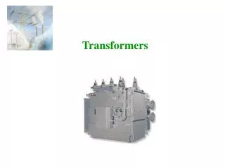
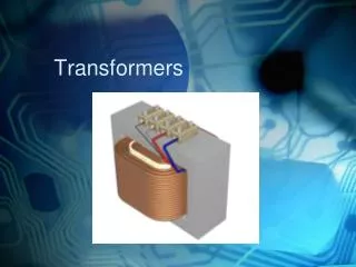
What is a transformer? • An electrical equipment used to transform ac voltages from one to another value • Device which works on the principle of electro-magnetism
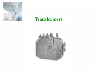
Transformer • Widely used in power systems • Possible to transmit power at an economical transmission voltage and • Utilize power at an economic effective voltage
Why do we needtransformers in an electrical system? • Bulk of generating voltage limited to 15 ~ 25 kV, though power generated is in hundreds of MW • Impractical to distribute power at generated voltage: • High power loss in transmission/distribution • Greater cross section of conductors • Higher voltage drop in distribution system
Why do we needtransformers in an electrical system? • High transmission voltage required - achieved by using transformers • Convert AC voltage of any value to any desired value - Use suitable turns ratio for transformer windings • Applicable only for AC circuits, cannot be used for DC circuits
How can transformers regulate voltage in electrical powersystem? • Maintaining constant voltage for equipment vital for many power consumers when supply is availed from utility grid - especially whose processes are critical • Simple transformer law - Primary to secondary voltage ratio equal to its primary to secondary turns ratio and vice versa • Change of turns-ratio accomplished by adding/ subtracting required number of turns to either primary or secondary winding
Transformers for Oil & Gas Applications • Transformers for oil & gas applications may range between 250kVA and 40MVA • May be air-cooled or water cooled with indoor and outdoor enclosure • Generally fall under two categories of construction – Dry type and liquid immersed type • Air-insulated and solid insulated constructions are included under the dry type
Transformers for Oil & Gas Applications • Epoxy Cast dry type transformer • This type does not use insulation papers in the windings • Instead, pure epoxy resin reinforced with glass fiber rovings are wound directly with the wire • Winding processes controlled by advanced electronics also ensure even distribution and high levels of precision
Transformers for Oil & Gas Applications • Vacuum cast coil dry type transformer
Transformers for Oil & Gas Applications Maxi cast-resin transformer • Combines advantages of liquid-filled & dry type transformers • Safe, powerful, and environmentally safe alternative to liquid-filled transformers Siemens cast resin power dry-type transformer
Transformers for Oil & Gas Applications Liquid immersed transformers
Transformers for Oil & Gas Applications Small, medium and large power Transformers • Small power transformers are distribution transformers with a range of 5 to 30 MVA, and a maximum service voltage of 145 kV. • Medium power transformers with a power range between 40 and 250 MVA and a voltage over 72.5 kV are used as network and generator step-up transformers. • Depending on onsite requirements, transformers in the power range above 200 MVA can be designed as multi-winding transformers or autotransformers, in 3-phase or 1-phase versions. Small Medium Large
Types of transformers • Generator transformer • Earthing transformer • Station transformer • Unit transformer
Generator Transformer • Important link between generator in power generating station and transmission lines • Normally step-up transformers • Most present day power generators generate voltages between 10 kV to 30 kV • Stator voltage kept as high as possible to keep current within manageable values • Generators of around 150 MW generate power at 11 ~ 13.8 kV - Line currents around 9000 amperes at 0.85 power factor
Scheme forEarthing Transformer 400 kV Generator Transformer Earthing Transformer 23.5 kV Unit Transformer Generator 11 kV 11 kV
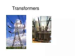
Role of transformers in transmission, distribution networks • Reduce transmission, distribution losses • Reduced size of transmission, distribution line conductors • Reduced voltage drops in transmission, distribution
What is magnetism? • Magnetism is a phenomena by which materials exert attractive or repulsive forces on other materials • A property governed by the atomic characteristics of the substance
Electricity and magnetism • Inter-related • Relationship is often called electromagnetism • Physics of electromagnetic field: a field which exerts a force on particles that possess the property of electric charge, and is in turn affected by the presence and motion of those particles
Current flowing in an electric conductor produces magnetic field in its vicinity Magnetic field linked to the medium in the vicinity of current varies depending on material of medium Further classified as Magnetic and Non magnetic depending on ability to retain / allow higher magnitude of this magnetic field Electricity & Magnetism
Similar to production of magnetic field by flow of external current, the same magnetic field also produces an electrical force when it is in vicinity of a good conductor which is not connected to any external source Called EMF (Electro motive force) induced in the conductor due to external magnetic field Electro Magnetic Induction
Electro-magnetic induction • Induced emf - Use magnetic field to produce electrical force when magnetic flux is in vicinity of good conductor • Induced emf classified as: • Dynamically induced emf • Statically induced emf
Basic theory of transformer • Statically induced emf - Emf induced in a stationary conductor due to a change in flux linkage arising from a change in the magnetic field around the conductor • Dynamically induced emf - Emf induced in a moving conductor when the conductor is moved in a stationary magnetic field • Statically induced emf is the basic principle used in a transformer
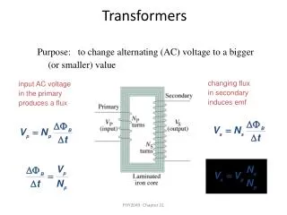
Transformer principle • AC voltage applied between terminals A1 and A2 • Voltage induced between terminals a1 and a2
Transformer principle Magnetic flux links primary and secondary windings
Transformer principle • Applied voltage causes current to flow in first winding • Current variation in coil creates varying magnetic flux in core material • Varying magnetic flux in core induces voltage in second winding • Load connected across terminals a1 and a2 causes current flow in load • Voltage induced in secondary winding depends on its number of turns in relation to number of turns in primary winding T1 V1 I2 ------------- = ------------ = ------------ T2 V2 I1
Transformer Principle • Primary current is small under open circuit conditions so that applied voltage is almost equal and opposite to the emf induced in P. Hence, • Secondary output power is almost equal to the primary input power and can be expressed as V1 I1 Cos 1 = V2 I2 Cos 2
Transformer principle • Secondary voltage can be reduced/ increased by changing turns ratio between primary and secondary winding • Primary current increases/ decreases in accordance with secondary load current • This balance of ampere-turns in primary and secondary windings of transformer holds the key for transformer action and design
Important points about transformers • Used to transfer energy from one AC circuit to another • Frequency remains same in both circuits • No ideal transformer exists • Also used in metering, protection applications - Current transformer (CT), potential transformers (PT) • Used for isolation of two different circuits (isolation transformers) • Transformer capacity expressed in VA (Volt amperes) • Transformer polarity indicated by dots
Types of transformers • Core Type transformers are the most common type employed in majority of transformers in the world • Shell Types are mostly employed for furnace transformers • Windings are normally made of electrolytic grade Copper and the metallic parts are basically made of steel
Types of transformers By type of construction: • Core type: Windings surround a considerable part of the core • Shell type: Core surrounds a considerable portion of the windings
Types of transformers (By method of cooling) • Oil filled self-cooled: Small and medium sized distribution transformers • Oil filled water-cooled: High voltage transmission line outdoor transformers • Air-Cooled type: Used for low ratings and can be • Natural air circulation (AN) type • Forced circulation (AF) type • Dry type transformer
Types of transformers (By method of application) • Power transformer: Large transformers used to change voltage levels and current levels as per requirement. Power transformers. Usually used in distribution or a transmission line • Potential transformer: Precision voltage step-down transformers used along with low range voltmeters to measure high voltages • Current transformer: Used for measurement of current where current carrying conductor is treated as primary transformer. Isolates instruments from high voltage line, as well as step down current in a known ratio • Isolation transformer: Used to isolate two different circuits without changing voltage level or current level
Dry Type Transformers • No oil in the transformer • Air cooled and built for various insulation classes up to class H • Insulation between High and Low voltage windings by FRP (Fire Retardant Paper) cylinders • Epoxy, Cast Resin & VPI are the most common
Dry Type Transformers • Normally indoor Type in suitable enclosures • Limited to capacities up to 10 MVA and up to 36 KV class • Lesser thermal efficiency and lesser over load capacities compared to oil filled types
Transformer Parts Main parts of a transformer may be grouped as below: • Transformer Core • Transformer windings • Winding Insulation • Cooling medium • Transformer Tank/Enclosure • Transformer accessories for measurements and protection
Core Laminations • Transformer cores are not made of solid steel but are normally built up in the form of laminations to reduce the eddy current losses • Made in the form of E’s and I’s (Also T’s) to get the closed magnetic circuit of the core
Transformer Core • Cold Rolled Grain Oriented (CRGO) steel • Low reluctance, low loss flux path • Low hysteresis loss • Phosphate coated, lacquered laminations - Reduced eddy current loss Silicon steel stamping usually shaped like "E" and "I" Typical Transformer Stampings
Typical Lamination Sections Cruciform type
Core Laminations • Circular cross section formed by combining rectangular laminations of different cross sections to form into an overall circular shape • A maximum of 95% fill can be possible by planning the number of steps and choosing proper thickness of core laminations
Boltless construction normally employs mitred joints with overlaps of 450. Mitred Joints of Transformer Core
Flux direction follows orientation of grains more smoothly with least resistance in magnetic core having mitred joints. Reduces power required to pass magnetic flux in direction of grain orientation Comparison of Flux Orientations
Hysteresis Loop • Magnetic Materials have characteristic called Hysteresis • Ability to retain certain amount of flux (B) even if magnetizing force (H) is removed or made Zero • Hysteresis loop is formed when H completes a full cycle