Download
1 / 38
400 likes | 440 Views
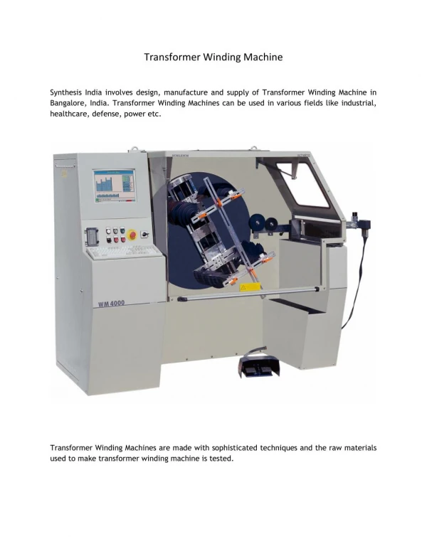
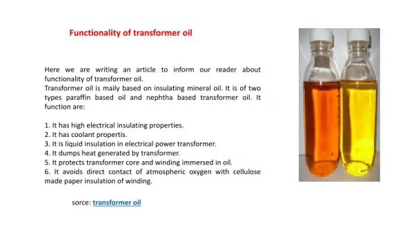
Transformer -Types & Applications. Module 1. What are transformers?. Transformers are electrical devices used to convert or "transform" AC voltage from one level to another. (high to low or low to high) Input and output are AC They do this by the principle of electromagnetic induction.

E N D
Transformer -Types & Applications Module 1
What are transformers? • Transformers are electrical devices used to convert or "transform" AC voltage from one level to another. (high to low or low to high) • Input and output are AC • They do this by the principle of electromagnetic induction
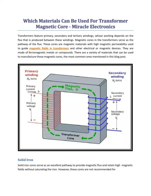
Parts of a Transformer A transformer consists of 3 basic components • Primary Coil or Primary Winding : It is an electrical wire wrapped around the core on the input side • Secondary Coil or Secondary Winding: It is an electrical wire wrapped around the core on the output side • Core : A ferromagnetic material that can conduct a magnetic field through it. Example: Iron
Transformer Operation • An electrical transformer normally consists of a ferromagnetic core and two coils called "windings". • A transformer uses the principle of mutual inductance to create an AC voltage in the secondary coil from the alternating electric current flowing through the primary coil. • The voltage induced in the secondary can be used to drive a load.
What is Mutual Inductance? • The principle of mutual inductance says that when two electrical coils are placed near to each other, AC electrical current flowing in one coilinduces an AC voltage in the other coil. • This is because current in the first coil creates a magnetic field around the first coil which in turn induces a voltage in second coil
The transformer improves the efficiency of the transfer of energy from one coil to another by using a core to concentrate the magnetic field. • The primary coil creates a magnetic field that is concentrated by the core and induces a voltage in the secondary coil
Turns Ratio • The voltage at the secondary coil can be different from the voltage at the primary. This happens when the number of turns of the coil in primary and secondary are not the same • The Turns Ratio (TR) is the ratio of the number of turns in the primary coil to the number of turns in the secondary coil
Formulas • TR= Vp / Vs • Also TR= Np /Ns • So we can say Vp / Vs = Np /Ns Also Vp/Vs=Is /Ip
Problems • A transformer has a primary voltage of 230v and turns ratio of 5:1. Calculate the secondary voltage • A transformer has 200 turns in the primary, 50 turns in the secondary, and 120 volts applied to the primary (Vp). What is the voltage across the secondary (V s)?
More Problems…. • There are 400 turns of wire in an iron-core coil. If this coil is to be used as the primary of a transformer, how many turns must be wound on the coil to form the secondary winding of the transformer to have a secondary voltage of one volt if the primary voltage is five volts? • A 12 volts transformer has 20 turns in the primary, 5 turns in the secondary. What is the voltage across the primary side (VP)?
Lab Activity 2 • Complete Pages 19 -22 of Module 1
Input Power and Output Power of a Transformer • Under ideal conditions input power and output power should be the same. But there is power loss between the primary and secondary and so practically they are not exactly equal. • So, Pin = Pout + Ploss
Transformer Efficiency • The power loss is converted to heat . The heat produced can be found by calculating the transformer efficiency.
Transformer Types • Isolation Transformer • Autotransformer
Isolation Transformer • In isolation transformer, the primary and secondary are physically isolated (no electrical connection)
Advantages of Isolation Transformer • Voltage spikes that might occur on the primary are greatly reduced or eliminated in the secondary • If the primary is shorted somehow, any load connected to the secondary is not damaged • Example: In TV monitors to protect the picture tube from voltage spikes in main power lines
Autotransformers • An autotransformer uses only one coil for the primary and secondary. • It uses taps on the coil to produce the different ratios and voltages.
The Control Transformer • A control transformer is used to reduce voltage from the main power line to a lower voltage that operates a machine’s electrical control system.
The Control Transformer • The most common type of control transformer has two primary coils (H1H2 and H3H4) and one secondary coil (X1X2). Note that the primary windings are crossed
To get 120V at the secondary from 240 V at the primary using a control transformer
To get 120V at the secondary from 480 V at the primary using a control transformer
Problem 1 • Connect the primary coils in parallel and calculate the secondary voltage if the primary voltage is 48 Volts and the number of turns in each primary is 50 turns and the secondary has 25 turns.
Problem 2 • Connect the primary coils in series and calculate the secondary voltage if the primary voltage is 48 Volts and the number of turns in each primary is 50 turns and the secondary has 25 turns.
Problem 3:Make connections in the transformer coils to produce a turns ratio of 1:1. Use both primary and secondary coils.
Problem 4:Make connections in the transformer coils to produce a turns ratio of 2:1. Use both primary and secondary coils.