Download

1 / 23
230 likes | 370 Views
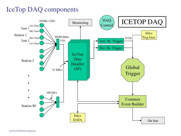
DAQ Map of Electronic Components. R. Suleiman May 06 , 2014. Mott DAQ. Mott DAQ crates. VME Crate. Mott NIM Crate 1. Mott NIM Crate 2. VME CRATE. Gate. 1 In. 1. 1. 17 BFM 18 Mott DetTr. L1A LEMO 4. Common. LN1. L1A ECL 4. TRG IN. TRG IN. BUSY. INH. Opsmdaq0.

E N D
DAQ Map ofElectronic Components R. Suleiman May 06, 2014
Mott DAQ crates VME Crate Mott NIM Crate 1 Mott NIM Crate 2
VME CRATE Gate 1 In 1 1 17 BFM 18 Mott DetTr L1A LEMO 4 Common LN1 L1A ECL 4 TRG IN TRG IN BUSY INH Opsmdaq0 nT_Settle
Mott Detector Trigger Logic Diagram Shaping Delay = 4 ns Thresholds: LEFT: -25 mV RIGHT: -25 mV UP: -30 mV DOWN: -30 mV FADC S1 E Detector FANOUT Timing DISC S1 Shaping Delay = 2 ns Thresholds: LEFT:-25 mV RIGHT: -29 mV UP: -27 mV DOWN: -42 mV S1 L S1 R U Mott DetTr D Timing DISC ΔE Detector Veto Octal DISC Delay Box FANOUT Thresholds: LEFT: -185 mV RIGHT: -189 mV UP: -185 mV DOWN: -186 mV FADC
HELICITY SIGNALS T_Settle Pair -Sync Pattern-Sync Delayed Helicity
CHANNEL ASSIGNMENT – MOTT FADC Signals on Scope Mott Trigger Left E Left ∆E Signals in FADC Data
CONTROL CHANNEL ASSIGNMENT – GATED SCALER S1 • nT_Settle Trigger Setup: • nT_Settle Trigger is delayed by 0.4 µs • LNE is delayed by 0.2 µs nT_Settle nT_Settle LNE Delayed TID nT_Settle Trigger (Scalers )
Beat Frequency Modulation (BFM) – Hansknecht (new) BFM after -450 mV offset BFM BFM, after 0.01 µF Coupler BFM after -200 mV discrimination (TDC) BFM in FADC, Range=1.0 V
Beat Frequency Modulation (BFM) – Musson (old) BFM after -140 mV offset BFM, after 0.01 µF Coupler BFM after -145 mV discrimination (TDC) BFM in FADC, Range=0.5 V