Download
1 / 68
690 likes | 949 Views
NVIS, Another Look. Fixed Installation Tri-Band. Tom Sanders, W6QJI Ed Bruette, N7NVP. Near Vertical Incident Skywave. Cloud Warmer. What is NVIS?. Propagation Theory. NVIS Effect. 300 Mile Coverage. 5/8 Wave 75 Meter Vertical Radiation Pattern. Propagation Considerations.

E N D
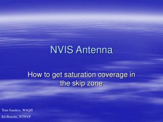
NVIS, Another Look Fixed Installation Tri-Band Tom Sanders, W6QJI Ed Bruette, N7NVP
Near Vertical Incident Skywave Cloud Warmer What is NVIS?
Propagation Considerations • “D” layer losses • Ionospheric scattering for vertical propagation • Importance of critical frequency
Bandwidth 75 Meters • 4005 – 1.5:1 • 3950 – dip • 3875 – 1.5:1
Bandwidth 60 Meters • 5390 – 1.5:1 • 5360 – dip • 5317 – 1.5:1
Bandwidth 40 Meters • 7295 – 1.5:1 • 7245 – dip • 7225 – 1.5:1
Dual Band • Yes; you can remove the 60 Meter elements!
How It Went Together • Materials • Construction • Modifications
Parts List • 1 - Feed point - 50 Ohm • #14 insulated stranded wire – 280’ • 3 - ½” x 10‘ PVC cut to length • 2 – Insulators • Tie wraps • 3/16” rope cut to length • Coax to the shack
Spreader Lengths • 2 – 17” Next to center insulator • 2 – 34” 2nd from center insulator • 2 – 50.5” End of 40 M element • 2 – 25.25” End of 60M element • Another spreader could be used between the center insulator and the end of the 40M element
Element Lengths • 75 Mtr legs = 57.33 ft • 60 Mtr legs = 45.4 ft • 40 Mtr legs = 34.25 ft • Prune these lengths to meet your ground conditions
60 Meter tension UV resistant line
Beamwidth • 75 Mtrs 38 deg. To 142 deg. • 60 Mtrs 36.5 deg To 143.5 deg. • 40 Mtrs 34 deg. To 146 deg.