Download

1 / 50
580 likes | 1.02k Views
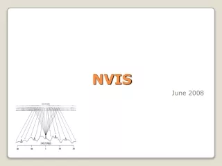
NVIS. NVIS. What is NVIS ? Means N ear- V ertical I ncidence S kywave Opposite of DX (long – distance) Local - to - Medium Distance (0 – 250 mls). ‘Ordinary’ Propagation. Illustration courtesy of Barrett Communications Pty. ‘Ordinary’ Propagation.

E N D
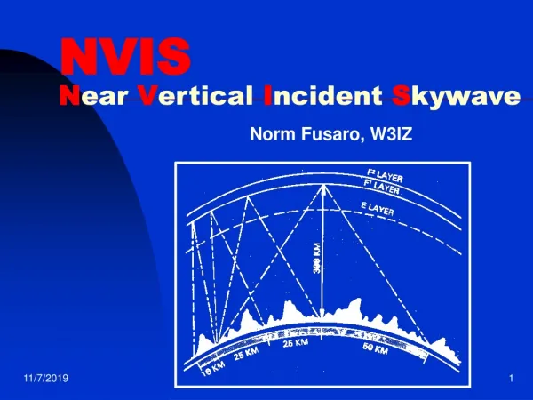
NVIS • What is NVIS ? • Means Near-Vertical Incidence Skywave • Opposite of DX (long – distance) • Local - to - Medium Distance (0 – 250 mls)
‘Ordinary’ Propagation Illustration courtesy of Barrett Communications Pty
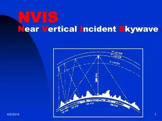
‘Ordinary’ Propagation • To travel a long distance, the signal must take off at a LOW angle from the antenna – 30 degrees or less • This is so that it can travel the maximum distance before it first arrives at the Ionosphere • Long gap before signal returns to earth – the part in between this and the end of the ground wave is the so-called Skip (or Dead) Zone
‘Ordinary’ Propagation Illustration courtesy of Barrett Communications Pty
NVIS Propagation Illustration courtesy of Barrett Communications Pty
NVIS Propagation • To travel a local - medium distance, the signal must take off at a HIGH angle from the antenna – typically 60 – 90 degrees • This returns from the Ionosphere at a similar angle, covering 0 – 250 mls • It thus fills in the Skip (or Dead) Zone – like taking a hose and spraying it into an umbrella !
NVIS Propagation Illustration courtesy of Barrett Communications Pty
Using NVIS successfully • HIGH angle of radiation from antenna • Minimise ground wave, as it will interfere with the returning skywave • Most importantly, CHOOSE THE CORRECT FREQUENCY BAND – go too high in frequency and your signal will pass through straight into space!
Choosing the right frequency • The Ionosphere – D, E, F1 & F2 layers • D and to a lesser extent, E layers attenuate and absorb signal • Best returns from F2 layer • At any one time we need to know the frequency of the F2 layer – The Critical Frequency or foF2 • Optimum frequency for NVIS work around 10% below this
The Ionosphere Illustration courtesy of the University of Ulster Communications Centre
NVIS - Frequency and Time • In practice, highest NVIS frequency can reach 10 MHz band. Lowest can go down down to1.81 MHz band • ‘Higher’ frequency band during day, ‘Middle’ frequencies afternoon/evening, ‘Lower’ frequencies at night • Frequencies also affected by time of year and period of sunspot cycle • For best results, these three different frequency ‘bands’ required
NVIS – The Critical Frequency • The Critical Frequency is the key to successful NVIS working • The Critical Frequency (or foF2) is the highest frequency at any one time that a signal transmitted vertically will be returned to earth. Anything above this passes into Space • As we are interested in vertical signals for NVIS, then the value of the Critical Frequency (foF2) at any one time is of great importance to us • How can we find or estimate foF2 ?
NVIS – Finding The Critical Frequency • Real-time web information from Ionosondes • Websites offering Critical Frequency predictions: – RAL STIF, IPS Euromaps • Software Propagation prediction tables or similar printed material: - W6ELprop etc. • Rule-of-thumb:- ‘higher’ band by day, ‘middle’ band afternoon/evening transition, ‘lower’ band nightime
Ionospheric Prediction Map Courtesy of RAL Short Term Ionospheric Forecasting Site
NVIS – For the Radio Amateur • In practice, 7 MHz (40m) usually ‘highest’ band • 3.5 MHz (80m) next lowest • 1.81 MHz (160m, ‘Topband’) the lowest • 80m and 160m strongly affected during the day by absorption from the D-layer, plus noise at night and varying times of the year • Need for a ‘middle’ transition frequency around 5 MHz
NVIS – The Antenna Side • Need high angle (60-90°) radiation for NVIS • Vertical no use – predominantly low angle • Half wave dipole at ‘text book’ height – 0.5 wavelength produces low angle radiation, BUT, if lowered to 0.25 wavelength or below, produces high angle radiation ! • Not too low, though – some earth losses. A reflector wire or earth mat can reduce this
Vertical = No High Angle Radiation Courtesy of ARRL Handbook
Horizontal dipole at ‘textbook’ height • Textbooks say that for a horizontal dipole to radiate low angle radiation, it must be half (0.5) a wavelength above ground • In the case of the lower bands such as 80 and 160m, this would be pretty high!
Low Horizontal dipole = High Angle • If the height of the dipole is lowered, the angle of radiation becomes higher and the low angle radiation starts to disappear • The optimum amount of high angle radiation is obtained at a quarter- (0.25) wavelength above ground • Going lower than 0.25 causes efficiency loss • In practice 0.25 – 0.15 wavelength heights used for NVIS
Low Horizontal dipole = High Angle Illustration courtesy of NVIS Communications (Worldradio Books)
NVIS – Monoband Antennas • The dipole is essentially a single band antenna • There are also a couple of special higher-gain single band NVIS antennas – Dipole with reflector The Shirley The Jamaica
NVIS – Dipole with Reflector Illustration courtesy of NVIS Communications (Worldradio Books)
NVIS – The Shirley Antenna Illustration courtesy of NVIS Communications (Worldradio Books)
NVIS – The Jamaica Antenna Illustration courtesy of NVIS Communications (Worldradio Books)
NVIS – Multiband Antennas • As mentioned earlier, at least three different frequency bands are needed for successful 24 hr NVIS operation and so multi or wideband antennas are used • Simple ones include long wire, inverted-L, Shallow (120°) Inverted-Vee Doublet with open feeder, full-wave low (0.15-0.25λ) horizontal loop (reflector could also be used below this) • Other multiband antennas can be used -
NVIS – The Fan Dipole Illustration courtesy of NVIS Communications (Worldradio Books)
NVIS – The AS2259 or ‘Collins’ Antenna Illustration courtesy of NVIS Communications (Worldradio Books)
NVIS – The Jumpered Doublet Illustration courtesy of NVIS Communications (Worldradio Books)
NVIS –Wideband Folded Dipole (T2FD) Antenna total length approx 90ft 600 Ω Terminating Resistance/Balancing Network 12 : 1 Stepdown Balun to 50 Ω Example – Barker & Williamson BWD 1.8 – 30 MHz Wideband Folded Dipole Courtesy of Barker & Williamson Manufacturing Inc.
NVIS – Mobile Operation • You can use a whip for NVIS – but NOT VERTICAL ! You can either a) Bend the whip back over the vehicle as flat as possible without breaking (see Military on TV) b) Bend the whip back away from the vehicle at least 45°- OK when stationary, but not recommended mobile ! Keep your distance ! • You can use loops – either a) A fore – aft loop or b) Magnetic Loop Take care as high RF voltages exist on certain parts of these antennas
NVIS – Tilt Angle Adaptor Illustration courtesy of NVIS Communication – Worldradio Books
NVIS – Codan’s Whip Method Illustration courtesy of Codan Pty.
NVIS – The Fore – Aft Loop (WA6UBE) Photos courtesy of Patricia Gibbons, WA6UBE
NVIS – The Magnetic Loop (Russian Style !) Photo PA3EQB
NVIS – The Magnetic Loop (Aussie Style !) Photo Q-Mac Pty
NVIS – The Magnetic Loop (O.T.T. Style ?) Photo WB3AKD
A few other aspects of NVIS • NVIS in WW II For D-Day : Successful communications between Operations HQ at Uxbridge, forward control ship USS Ancon and landing parties achieved using horizontal antennas and high-angle skywave, following poor results with verticals – done by Dr. Harold Beverage (of long antenna fame !) Germans also used NVIS Mobile antennas in WW II • ‘Tone’ Burst’s view of NVIS !
NVIS on D-Day Illustration courtesy of NVIS Communication, Worldradio Books
WWII German Radio Vehicle with NVIS Antenna Photo Schiffer Publishing/Tactical Link
‘Tone’ Burst’s View of NVIS RSGB Radio Today Sept 2000
ALE : Automatic Link Establishment • ALE scans and tests sets of frequencies – usually in several bands - for a particular path or net until it finds a frequency that will support communications over the path. • Each radio in an ALE net constantly broadcasts a sounding signal and “listens” for other sounding signals generated by other net members • Analysis of these signals by processing determines the best frequency for communication at the time and this frequency is then selected automatically for operations
G4GUO’s ALE Controller Programme for PCs Charles Brain, G4GUO
Useful websites connected with NVIS • http://digisonde.oma.be/ Ionosonde at Dourbes, Belgium. Currently the nearest Real-Time Ionograms for foF2 Critical Frequency • http://ionosphere.rcru.rl.ac.uk/maps.htmRutherford Appleton Lab Space Weather Web – foF2 Prediction Map • http://www.ips.gov.auAustralian Space Weather agency. Several useful maps. Covers Europe • http://www.cebik.com/cb.html Some Notes on `Cloud Burners' (US term for NVIS antennas) • http://www.scn.org/IP/nwqrp/archives/apr98/nwqapr04.htm The `L' Mobile/Fixed Antenna • http://www.ether.ulst.ac.uk/projects/hf_prop.html University of Ulster Communications Engineering Centre NVIS page • http://www.codan.com.au/ Codan Communications (Australia) HF SSB & Satellite • http://www.iinet.net.au/~barrett Barrett Communications ( Aus.) Commercial HF SSB • http://www.qmac.com/ Q-Mac Communications (Aus.) HF SSB • http://www.chbrain.dircon.co.uk/ Charles Brain, G4GUO's Website. Contains ALE Programme and other very interesting digital speech experiments • http://www.wunclub.com/files/aleinfo.html World Utility Newsletter - Excellent ALE Article & Frequencies • http://www.raynet-hf.net/ RAYNET HF Team website. Lots of useful information • http://www.tactical-link.com/Interesting US Amateur NVIS site with a Military leaning
NVIS - Summary • Covers 0 – 250 mls using High-Angle (60-90°) Skywave • Choice of Correct Frequency Band just below the Critical Frequency is most important. • Antenna must be horizontal, not vertical (with the exception of magnetic loops) • Antenna must be low – between 0.25 and 0.15 of a wavelength above ground • An NVIS antenna has omnidirectional radiation • Multiband antenna (at least three bands) needed for 24hr NVIS coverage
NVIS - The End BJ Skips, Wigan
NVISNear-Vertical IncidenceSkywave Lecture by Gordon L Adams, G3LEQ Graphics by Paul D Gaskell, G4MWO Blandford November 2002