Download
1 / 61
710 likes | 1.09k Views
NVIS Antenna. How to get saturation coverage in the skip zone. Tom Sanders, W6QJI Ed Bruette, N7NVP. Problem statement.

E N D
NVIS Antenna How to get saturation coverage in the skip zone Tom Sanders, W6QJI Ed Bruette, N7NVP
Problem statement During disasters, WA communicators need to be able to reliably communicate with W7EMD at Camp Murray (State EOC) & other sites around the region via HF on 75 (Pri.), 60 and 40 mtrs (Sec.)
Goal • Traffic quality statewide communications using a single transportable antenna and a 100 W transmitter without an external tuner
Desirable attributes • Resonant at 7245 kHz, 5373 kHz and 3985 kHz • Omni-directional • Coverage of WA, OR, ID and BC • Portable • Easy for one person to erect
Near Vertical Incident Skywave Cloud Warmer What is NVIS?
The Technical End Of Things • Dr. Jelinek’s design • Modifying the original design to work on 75, 60 & 40 meters without a tuner • Tweaking for optimum performance
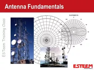
NEC2 Considerations • Original design using EZNEC replaced by NEC2 (Numerical Electromagnetic Code) • Derived from original NEC Provides accurate gain data for radiators very close to the ground • Gain figures vary with ground conditions
Propagation Considerations • “D” layer losses • Ionospheric scattering for vertical propagation • Importance of critical frequency
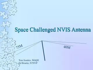
Element lengths • 75 Mtr legs = 58.32 ft • 60 Mtr legs = 43.00 ft • 40 Mtr legs = 34.08 ft • Prune these lengths to meet your ground conditions
60 Meter Power Considerations • 50W ERP limitation • Antenna gain • Feedline loss • Using this design, run a 100W radio at full power • QST Feb. 2004
How it went together • Materials • Construction • Modifications
Parts list • 2 1.5 in x 10 ft Schedule 40 PVC pipe – cut to 7.5 ft lengths • 1 1.5 in. compression coupler (joint connector) • 1 1.5 in. slip coupler • 2 1 in x 10 ft Schedule 40 PVC pipe – cut to 2.5 ft lengths (6 ea needed) • 6 1 in end caps • 6 5/8 in Schedule 20 PVC pipe – Cut to 6 in lengths – Drill hole for wire (6 ea needed) • 1 6 ft “T” fence post (fits inside center support)
Parts list (Cont.) • 6 18 in metal stakes • 1 50 Ohm feed point (Dipole center insulator) • 275 ft antenna wire – insulated 14 ga. • 2 8.5 in. wire pig tails – transition from feed point to wire elements • 2 Short non-conductive strain reliefs • 2 Split bolts or 5 hole grounding bars • Coax to reach the transmitter
Does it work? • Ed – Like gang busters! • Tom – S meter pin buster! • Field Day – Proved the theory. Worked WA, OR, ID, MT and CA as for South as Orange Co. Heard stations outside that radius but couldn’t work them • Day to day operations – Not bothered by distant stations as much as those with higher antennas