Download
1 / 37
370 likes | 531 Views
Photoinjector Performance M. Farkhondeh MIT-Bates Linear Accelerator Center Middleton, MA 01949, USA ASAC Review , September 18, 2003. Motivation for choice of beam parameters Photoinjector requirements RF cavity design Sensitivity studies Summary.

E N D
Photoinjector Performance • M. Farkhondeh • MIT-Bates Linear Accelerator Center • Middleton, MA 01949, USA • ASAC Review , September 18, 2003 • Motivation for choice of beam parameters • Photoinjector requirements • RF cavity design • Sensitivity studies • Summary
Motivation for choice of beam parameters • Emittance • Charge per bunch • long pulse: for narrow line width seeding, • 1 kA, 1ps 1 nC • short pulse:with 1-10 fs seed laser, 10’s of fs e-beam • 1 kA, ~ 200 fs 200 pC • Brightness vs total charge • Repetition rate ~ 1 kHz per beam line
5 5 5 3 3 4.5 4.5 4.5 4 4 4 2.5 4) 3.5 2.5 - 3.5 • Importance of electron beam emittance in SASE saturation lengths 3.5 120 3 70 80 60 70 100 40 50 50 80 40 60 110 120 90 110 90 3 100 /E (x1.0e dE/E (.01%) 3 Peak current (kA) Peak current (kA) 2 2.5 2.5 2 2.5 dE 2 2 l=0.3 nm 2 40 l=0.3 nm 50 1.5 50 40 90 1.5 100 1.5 110 90 60 1.5 80 120 100 70 110 1.5 60 70 80 120 1 1 1 0.2 0.4 0.6 0.8 1 1.2 1.4 1 0.2 0.4 0.6 0.8 1 1.2 1.4 1 0.2 0.4 0.6 0.8 1 1.2 1.4 0.2 0.2 0.4 0.4 0.6 0.6 0.8 0.8 1 1 1.2 1.2 1.4 1.4 Norm. emittance (mm) Norm. emittance (um) Sensitivity to emittance regardless of peak current and energy spread. Photoinjector Emittance • eN limits FEL performance if :
Slice parameters vs injector peak current 10 pC 5 A 15 A Data taken at BNL’s DUV-FEL with s-band injector. 50 A 25 A High current cases demonstrate both slice emittance growth and phase space distortion.
1 1 0.8 0.8 Intensity (A.U.) 0.6 0.6 Intensity (A.U.) 0.4 0.4 0.2 0.2 0 0 - - 10 10 - - 5 5 0 0 5 5 10 10 Time ( Time ( ps ps ) ) Beam brightness for imperfect distributions Parmela simulation Laser time profile Modulation on initial laser time profile simulates realistic, imperfect beam.
8 8 8 7.9 7.9 7.9 ) ) ) MeV MeV MeV 0.1 nC 0.5 nC 1.0 nC 7.8 7.8 7.8 K.E. ( K.E. ( K.E. ( 7.7 7.7 7.7 7.6 7.6 7.6 7.5 7.5 7.5 - 10 - 5 0 5 10 - 10 - 5 0 5 10 - 10 - 5 0 5 10 Time ( ps ) Time ( ps ) Time ( ps ) 40 80 8 30 60 6 Current (A) Current (A) Current (A) 20 40 4 10 20 2 0 0 0 - 10 - 5 0 5 10 - 10 - 5 0 5 10 - 10 - 5 0 5 10 Time ( ps ) Time ( ps ) Time ( ps ) 6 10 2 8 ) ) 4 ) 1.5 6 keV keV keV ( ( ( dE dE 4 dE 2 1 2 0 0 0.5 - 10 - 5 0 5 10 - 10 - 5 0 5 10 - 10 - 5 0 5 10 Time ( ps ) Time ( ps ) Time ( ps ) Longitudinal phase space
Time ( ps ) Time ( ps ) Time ( ps ) (um) (um) (um) 0.5 0.5 0.5 0.4 0.4 0.4 Emitnx Emitnx Emitnx 0.3 0.3 0.3 0.2 0.2 0.2 - 10 - 5 0 5 10 - 10 - 5 0 5 10 - 10 - 5 0 5 10 Time ( ps ) Time ( ps ) Time ( ps ) 0 0 0 - 10 - 10 - 5 - 20 alphaX alphaX alphaX - 20 - 30 - 10 - 30 - 40 - 50 - 40 - 15 - 10 - 5 0 5 10 - 10 - 5 0 5 10 - 10 - 5 0 5 10 Time ( ps ) Time ( ps ) Time ( ps ) 100 150 50 80 40 (m) (m) (m) 100 60 30 betaX betaX betaX 40 20 50 20 10 0 0 0 - 10 - 5 0 5 10 - 10 - 5 0 5 10 - 10 - 5 0 5 10 Time ( ps ) Time ( ps ) Time ( ps ) Transverse phase space
Simulation results Q(nC) 0.1 0.5 1.0 B ( nC/mm2 ps MeV) 18.5 3.9 2.4 Transverse phase space Defining the 6D emittance the beam brightness is Brightness is the important parameter for FEL performance and not the total charge by itself.
Photoinjector parameters • Frequency: 1.3 GHz • Emittance: 0.3/0.8 mm • Charge: 0.2/1.0 nC • Timing: 20 ps pulse • peak current 10/50 A • Repetition rate: 10 kHz • Phase stability: 0.5 deg • Laser timing: 0.01 deg (20 fs)
RF Gun cavity design • RF photocathode gun design • Cavity design (shaped vs. pillbox) • Peak and average power • Photocathode and laser • Independent phase and amp. control for each cell
Photoinjector • photocathode: Cs2Te excited at 266 nm (QE>1%) • Cavity : 2.5-cell copper RF cavity at room temperature. • Laser system: 4th harmonic of 1064 nm F. Kaertner presentation Yb:fiber amplifier IPG-Photonics 20ps, 10mJ, 1-10 kHz @ 1064 nm 4th-Harmonic 20ps, 1mJ, 1-10 kHz @266 nm
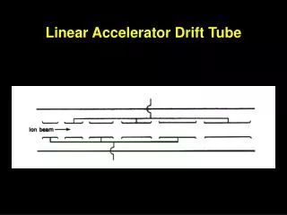
Independent phase/amplitude controls Photocathode 2.5 cell RF photoinjector cavity Power density < 100 W/cm2 55 MV/m in ½ cell and 43 MV/m in cells 2 and 3 Design derived from work by J. Rose (BNL) and R. Rimmer (LBL)
Pmax~100 W/cm2 Emax= 88 MV/m First (1/2) cell RF cavity
RF Gun Cavity ½ Cell Superfish: Peak power=200W*552=600 kW
RF gun cavity full cell Superfish: Peak power=860W*432=1.5 MW
RF Gun Specifications Power Density < 100 W/cm2
Beam Sensitivity studies • Parmela Simulations • Studied effects of jitters in photocathode laser phase/time and in ½ cell RF phase and amplitude. This helped to specify stability requirements in phase and amplitude for laser and RF. • Laser timing jitter • RF Gun (1/2 cell) • Phase jitter • Field gradient amplitude jitter
Compressor Chicane RF Gun Quad triplet Quad triplet Cryomodule #1 Cryomodule #2 Linearizer Quad triplet Cryomodule #3 Injector
Photoinjector Quad triplet RF Gun Cryomodule #2 Chicane Cryomodule #3 Linearizer Fcryo3 - Fcathode Beam Jitter Studies Cryomodule #1
0.01 deg (20 fs) Laser phase jitter study dt=20 fs (0.01 deg) in beam ~0.01 deg. (20 fs) in gun laser phase stability is required
dt=20 fs (0.01 deg) dE0=0.25 MV/m or 5x10⁻³ in RF amplitude is required. ½ cell RF amplitude jitter study
½ cell RF Phase jitter study 20 fs (0.01 deg) in beam dF=0.5 deg in RF phase stability
Summary of stability study Based on dF < 0.01 deg (20 fs)and dE/E < 5 x 10⁻³
Summary • Photoinjector is based on 2.5-cell shaped copper cavity at 1.3 GHz, Cs2Te excited at 266 nm with 4th harmonic of 1064 nm. • Described motivation of choice of parameters, particularly the advantage of low bunch charges. • Jitter study using PARMELA resulted in specification of the stability requirements in phase of photoemission laser as well as the amplitude and phase of the ½ cell RF. • Next steps • Integrate Parmela with linac simulations. • Work with LBL to develop LUX injector concept.
RF Gun cavity design I (mA)= QE*P(mW)*l(nm)/1240 For p=1 W, l= 750, I=6.4 mA For l=266, QE=0.01, 1mJ, dt=20 ps
Cryomodule 1 Cryomodule 2
RF Photo-Cathode Gun Cu or Mg or CsTe2 photocathode Pulse: 10 ps FW UV Energy: 0.1 mJ Wavelength: 266 nm ~80 MV/m e- Emittance: 1 mm Charge: 100 pC 5-7 MeV Superfish study of RF cavity full cell half cell Courtesy of P. Emma, SLAC
Pulse Structure Options Linac RF CW linac Pulsed linac Gun RF pulses (10 kHz, 3 us) One beam pulse/gun RF pulse Each beam line receives ~ 1 kHz CW SC linac Beam pulses (1 ms apart), in ~1 kHz bursts/sec Each beam line receives ~ 100 Hz bursts/sec Pulsed linac • Gun drive laser and RF. (Rep. rates and duty cycles) • Linac RF (pulsed or CW)
½ cell RF Phase jitter study dW=0.01 MeV dF=0.10 deg in RF phase stability
Gun RF amplitude jitter study dW=0.01 MeV in beam dE0=0.03 MV/m or 5x10⁻⁴ in RF amplitude is required
DE/E DE/E DE/E Over-compression Under-compression 2sz0 z, time z z 2sz V = V0sin(wt) Dz = R56DE/E RF Accelerating Voltage Path Length-Energy Dependent Beamline Magnetic Bunch Compression Courtesy John Galayda, SLAC / SSRL
Requirements and Parameters(LUX) • 1.3 GHz operating frequency • 8-10 MeV output energy • 10 kHz pulse repetition rate • 1-3 ncoulomb charge, 20 psec pulse length • Stability numbers
Modified Cell 1 Shape Larger Radius Larger Radius
Electron Gun Courtesy X.J.Wang
Directly Diode-pumped Photo-Injector To achieve a homogeneous e-beam bunch Temporal: Flat-top shaped Yb:fiber amplifier IPG-Photonics 20ps, 10mJ, 1-10 kHz @ 1064 nm 4th-Harmonic 20ps, 1mJ, 1-10 kHz @266 nm Acusto-Optic Programable Pulse Shaper (Dazzler, Fastlight) Yb:YAG, 1ps rep. Rate 100 MHz Pulse Selector