Download
1 / 36
360 likes | 585 Views
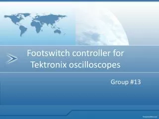
Footswitch controller for Tektronix oscilloscopes. Group #13.

E N D
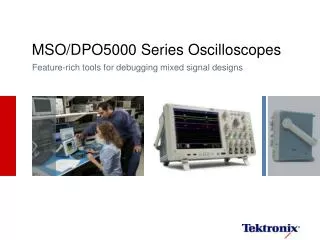
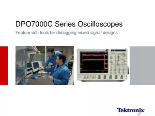
When an engineer or technician is using a Tektronix oscilloscope, they often have both hands busy probing a circuit board. Sometimes they need a “third hand” to operate the Oscilloscope. This need can cause some users to create Rube Goldberg type machines to manually press buttons, employ another operator to run the Oscilloscope, or find creative ways to tape down probes to free up hands. Without a solution, it can take users much longer to test circuits and collected required data.
Our solution to this problem is to implement a footswitch that will act as a third hand to control the Oscilloscope. (This was proposed as a capstone project for 2010)
The goal of this project is to design and build a working prototype of a footswitch and a software GUI that successfully integrates the footswitch with various Tektronix Oscilloscope. An ideal design would: • Be able to communicate with any Tektronix Oscilloscope. • Have multiple user configurable commands. • Have a minimum of 2 foot controls. • Have USB 2.0 interface. An individual momentary button’s functionality is expand by creating multiple mouse button type interaction. Separate actions include a short click, a long click and a double click. Both buttons may be pressed simultaneously. A 3rd On/Off type button is included, giving a total of 9 possible user input actions.
Long vs. Short vs. Double To determine pulse width times, we collected 30+ samples of each type of action each, for 4 different users. This data was collected on an Oscilloscope using a data logging program. Next a python script analyzed each set of waveforms to find the pulse widths and spacing for each interaction. Using Matlab to plot standard distributions of the results, the optimal values for pulse width duration for a short vs. a long click is and pulse space for a double click vs. two single click was derived. A short pulse is defined as less than 365mS pulse width. For double clicks, 275 spacing or less between two clicks is defined as a double. Because a action will be tied to a scope control command that may take several seconds to complete, it is less likely that the input action will be separate repeat clicks for the same command.
System View – Level 0 Footswitch Controller – Hardware
System View – Level 1 Footswitch Controller – Hardware
USB 2 Block Footswitch Controller – Hardware 5V Power Supply D+, D- for data lines
MCP2200 – USB Controller Block Footswitch Controller – Hardware GPIO [3..7] for transferring data Tx, Rx for UART status Use 12MHz crystal osc.
Buttons and Programmer Ports D2, D3 for momentary buttons Footswitch Controller – Hardware Ports D4 for on/off status button Port B3 for MOSI pin Port B4 for MISO pin Port B5 for SCK pin
Microcontroller – ATmega 8 Footswitch Controller – Hardware Use TQFN package Use 12MHz crystal osc.
Footswitch Controller – Hardware ~$20/Board ~$10 for components 2.80 inch Board layout 2.02 inch
Footswitch Controller – Hardware Test Plan for hardware Unit Tests USB Port, Power SupplyMCP2200 USB ControllerAtmega 8Button and Programmer Integration Tests Connection between USB Port and MCP2200 Connection between MCP2200 and Atmega 8Connection from button and programmer to ATmega8
ATmega8 - Functionality • Detect button states • Determine short/long/double pushed • Communicate with PC GUI through MCP2200 • Send commands to GUI • Handle MCP2200 status and commands from GUI
ATmega8 - Method • Using 1ms timer interrupt to poll button states • Using counter to count interval time • Determine press type by compare detected interval with preset intervals in EEPROM • Using command queue and ACK signal to send command to MCP2200
ATmega8 – Source code • C language • 5.59KB (69.9% Flash of ATmega8) • Pre-defined header for easily configure system later • Using AVRStudio 5 develop environment with Atmel libraries (io, delay, string, interrupt)
ATmega8 – Test plan Engineer requirement: “The device must measure the timing interval accurately with error less than 1%”. => Acceptance test: inject pulse with pulse width varies from 100ms to 900ms and record detected time.
Foot switch project GUI software design
Oscilloscope Communication • Uses VISA protocol for scope communication. • Common on Tektronix Oscilloscope platforms. • Commands are published by Tektronix in the form of Programmers manual for each oscilloscope family. • Test and Measurement Industry standard.
PC / USB communication • For communication to the PC, USB interface was used. • Made easy in the form of a dedicated USB bridge and dll libraries for the device “SimpleIO-UM.dll” device in conjunction with MCP2200 python module, developed in house. • Unnecessary to deal with USB Stack.
GUI behavior • Python 2.7.2 used for GUI development. • PyVisa 1.3 • Scope communication • Wxpython • GUI development • Numpy 1.6.1 • Curve data calculation • ScopeControl • Use PyVisa to send interpreted commands • MCP2200 • Communicate with PC over USB. “SimpleIO-UM.dll”
Interface layout • Tabs for each function • Tab dedicated to each button • Double Click • Scope connection / file placement • Script entry
Results / Lessons learned • What worked well • Engineers at Tektronix have been impressed. • What didn’t work • We were unable to get USB ports configured as COM port, - Adjustment routine dropped as a result. • Should have made silk screen larger / readable. • Post size was same as .632, same size as screws.