Download
1 / 37
390 likes | 717 Views
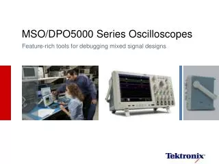
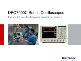
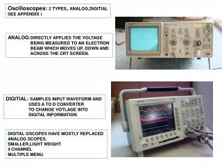
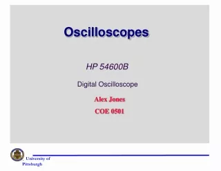
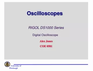
OSCILLOSCOPES. An oscilloscope (usually called a scope ) is a visual voltmeter with a timer (clock) that shows when a voltage changes. An analog scope uses a cathode ray tube (CRT) similar to a television screen to display voltage patterns.

E N D
OSCILLOSCOPES • An oscilloscope (usually called a scope) is a visual voltmeter with a timer (clock) that shows when a voltage changes. • An analog scope uses a cathode ray tube (CRT) similar to a television screen to display voltage patterns.
OSCILLOSCOPE DISPLAY GRIDSetting the Time Base • Most scopes use 10 graticules from left to right on the display. • Setting the time base means setting how much time will be displayed in each block. • A block is commonly referred to as a division. • The vertical scale has eight divisions. • If each division is set to equal 1 volt, the display will show 0 to 8 volts. • This is okay in a 0 to 5 volt variable sensor such as a throttle position (TP) sensor. • The volts per division (V/div) should be set so that the entire anticipated waveform can be viewed
OSCILLOSCOPE DISPLAY GRIDFrequency • Frequency is the number of cycles per second measured in hertz. • Engine RPM signal is an example of a signal that can occur at various frequencies. • At low engine speed, the ignition pulses occur fewer times per second (lower frequency) than when the engine is operated at higher engine speeds (RPM).
ELEKTRONIKOS ĮTAISAI 2009 4 Cathode-ray tubes The cathode ray tube (CRT), invented by GermanphysicistKarl Ferdinand Braun in 1897, is an evacuated glass envelope containing an electron gun (a source of electrons) and a fluorescent screen, usually with internal or external means to accelerate and deflect the electrons. When electrons strike the fluorescent screen, light is emitted. The electron beam is deflected and modulated in a way which causes it to display an image on the screen. The image may represent electrical waveforms (oscilloscope), pictures (television, computer monitor), echoes of aircraft detected by radar, etc. • A cathode ray tube (CRT) contains four basic parts: • electron gun, • focusing and accelerating systems, • deflecting systems, and • evacuated glass envelope with a phosphorescent screen that glows visibly when struck by the electron beam. VGTU EF ESK stanislovas.staras@el.vgtu.lt
Cathode-ray tubes. Cathodoluminescence The deflected and accelerated electron beam strikes a phosphorescent material on the inside face of the tube. The phosphor glows and the visible glow can be seen at the front of the tube. So cathodoluminescence is used in cathode ray tubes. Cathodoluminescent efficiency increases with increasing beam voltage. As a result of the screen bombardment free electrons are knocked out. To collect these electrons the inside surface of the glass balloon is coated by conducting aquadag layer. Usually this layer is connected to the accelerating anode. The screen of the CRT may be coated with aluminium on the inside and this coating is held at anode potential. Such an aluminized screen prevents the accumulation of charge on the phosphor and improves its performance increasing the visible output and reducing the effects of ion bombardment.
Functional Units a) Electron Gun b) Evacuated Tube c) Deflecting System d) Time Base e) Trigger Circuit
a) Heating Filament b) Cathode c) Grid d) Electron lens Link to figure Return
Cathode-ray tubes. Electrostatic focusing Two or more electrodes at different potentials are used to focus the electron beam. The electrostatic field set up between the electrodes causes the beam to converge. The focusing effect is controlled by varying the potential of the focusing electrode. Due to the focusing action electrons of the gun bombard the screen of the cathode ray tube at the same point. The system of converging and diverging lenses
ELEKTRONIKOS ĮTAISAI 2009 11 Cathode-ray tubes. Electromagnetic focusing Focus coil The focusing magnetic field is inhomogeneous and axial symmetrical. Cathode ray tube employing electromagnetic focus and deflection VGTU EF ESK stanislovas.staras@el.vgtu.lt
ELEKTRONIKOS ĮTAISAI 2009 12 Cathode-ray tubes. Electrostatic deflection Screen Electron beam Sensitivity VGTU EF ESK stanislovas.staras@el.vgtu.lt
ELEKTRONIKOS ĮTAISAI 2009 13 Cathode-ray tubes. Electromagnetic deflection Vertical deflection coil Glass balloon NI is the number of ampere-turns The sensitivity of a CRT with electrostatic deflecting system is in inverse ratio to U0. In the case of electromagnetic deflection it is in inverse ratio to . Using electromagnetic deflection we can obtain relatively great sensitivity and great deflection angle at high accelerating voltage . For this reason electromagnetic deflection is used in television picture tubes, requiring high-velocity electron beams necessary for bright display. VGTU EF ESK stanislovas.staras@el.vgtu.lt
ELEKTRONIKOS ĮTAISAI 2009 14 Cathode-ray tubes. Electromagnetic deflection VGTU EF ESK stanislovas.staras@el.vgtu.lt
ELEKTRONIKOS ĮTAISAI 2009 15 Cathode-ray tubes. Electromagnetic deflection VGTU EF ESK stanislovas.staras@el.vgtu.lt
ELEKTRONIKOS ĮTAISAI 2009 16 Cathode-ray tubes. Electromagnetic deflection VGTU EF ESK stanislovas.staras@el.vgtu.lt
Evacuated Tube • Vacuum space • Screen • Graphite inner wall • Shielded from electric and magnetic fields Return Link to figure
Deflecting System • X-plates • Y-plates • X and Y Deflection Amplifiers • X-shift Control • Y-shift Control • Sensitivity Control Return Link to figure
Time Base • Sawtooth potential difference • Time period control Return Link to figure
Trigger Circuit • Maintain a stable trace • Trig level control • Trigger time base • automatic triggering
USES OF CRO a) Voltmeter b) Display of waveforms c) Measurement of short time intervals d) Measurement of frequency e) Display of phase relationship f) Comparison of frequencies
Voltmeter • Calibration • D.C. voltmeter • A.C. voltmeter • Advantages over moving-coil voltmeters Return
Measurement of Short Time Intervals • Calibrate for the time base • Measure a very small time interval, e.g. measurement of sound speed in a metal rod
Measurement of Frequency • Signal applied to Y-plates • ‘Lock’ the trace • Choose a suitable time base • Determine the period, T • Calculate the frequency
Comparison of Frequencies • Lissajous’ figures • Frequency ratio
OSCILLOSCOPE DISPLAY GRIDDuty Cycle • Duty cycle refers to the percentage of on-time of the signal during one complete cycle. FIGURE 10-5 (a) A scope representation of a complete cycle showing both on-time and off-time. (b) A meter display indicating the on-time duty cycle in percent (%). Note the trigger and negative () symbol. This indicates that the meter started to record the percentage of on time when the voltage dropped (start of on-time). (Courtesy of Fluke Corporation)
OSCILLOSCOPE DISPLAY GRIDPulse Width • The pulse width is a measure of the actual on-time measured in milliseconds. • Fuel injectors are usually controlled by varying the pulse width. FIGURE 10-6 Most automotive computer systems control the device by opening and closing the ground to the component. (Courtesy of Fluke Corporation)
Setting The Time Base • Most scopes use ten divisions from left to right on the display. • The time base indicates how much time will be displayed in each division. • For example, if the scope is set to read 200 mV (0.200 V) per division, then the total displayed would be 2 sec (0.200 X 10 divisions = 2 sec).
OSCILLOSCOPE DISPLAY GRID External Trigger • An external trigger is when the trace starts when a signal is received from another (external) source. Trigger Level • The trigger level must be set to start the display. Trigger Slope • The trigger slope is the voltage direction that a waveform must have in order to start the display.
OSCILLOSCOPE DISPLAY GRID FIGURE 10-7 (a) A symbol for a positive trigger—a trigger occurs at a rising (positive) edge of the signal (waveform). (b) A symbol for a negative trigger—trigger occurs at a falling (negative) edge of the signal (waveform).
OSCILLOSCOPE DISPLAY GRIDMeasuring Battery Voltage with a Scope • One of the easiest things to measure and observe on a scope is battery voltage. • A lower voltage can be observed on the scope display as the engine is started and a higher voltage should be displayed after the engine starts.
OSCILLOSCOPE DISPLAY GRIDMeasuring Battery Voltage with a Scope FIGURE 10-8 Battery voltage is represented by a flat horizontal line. In this example, the engine was started and the battery voltage dropped to about 10 V as shown on the left side of the scope display. When the engine started, the generator (alternator) started to charge the battery and the voltage is shown as climbing.
GRAPHING MULTIMETER • A graphing multimeter, abbreviated GMM, is a cross between a digital meter and a digital storage oscilloscope. • A graphing multimeter displays the voltage levels on a display and a digital readout. FIGURE 10-9 A typical graphing multimeter.
CAN SCOPES MEASURE CURRENT? FIGURE 10-10 The fused jumper wire is connected to terminals 30 and 87 of the fuel pump relay socket. The current probe is shown clamped around the wire and the electronics in the probe convert the current reading into a millivolt signal that is used by the DSO to display the changing current waveform.
Cathode-ray tubes. Electron gun ELEKTRONIKOS ĮTAISAI 2009 37 An electron gun consists of a series of electrodes producing a narrow beam of high-velocity electrons. Electrons are released from the indirectly heated cathode. The intensity of the beam is controlled by variation of the negative potential of the cylindrical control grid surrounding the cathode. This electrode is called the modulator. The control grid has a hole in the front to allow passage of the electron beam. The electrons are accelerated and focused. VGTU EF ESK stanislovas.staras@el.vgtu.lt