Download
1 / 40
400 likes | 502 Views
Advances in Nonlinear NS FFAGS. C. Johnstone Fermilab /Particle Accelerator Corporation Trinity College, Oxford University Oxfor d, U.K. 9/13/ 2011. The International FFAG Collaboration: International Accelerator Laboratories and Universities. U.K. Daresbury Laboratory.

E N D
Advances in Nonlinear NS FFAGS C. Johnstone Fermilab/Particle Accelerator Corporation Trinity College, Oxford University Oxford, U.K. 9/13/ 2011
The International FFAG Collaboration: International Accelerator Laboratories and Universities U.K. Daresbury Laboratory. Manchester, Liverpool, Leeds, and Lancaster and Oxford University Imperial College Rutherford Appleton Laboratory John Adams Institute, Oxford Birmingham University Clatterbridge Centre for Oncology Beatson Oncology Centre Gray Cancer Center Japan KEK Kyoto University (KURRI) Osaka University U.S. Fermilab Brookhaven National Lab Lawrence Berkeley National Laboratory Illinois Institute of Technology Michigan State University Canada TRIUMF University of British Columbia Switzerland CERN France LPS Grenoble
Particle Accelerator Corp Accelerator and component design – FFAGs and synchrotrons, magnets, diagnostics Employees and collaborators Fred Mills (retired, Fermilab, built the first MURA FFAGs) C. Johnstone (Fermilab Richard Ford (Fermilab) V. Kashikhin (Fermilab) Shane Koscielniak (TRIUMF) Martin Berz (Michigan State University) Kyoko Makino (Michigan State University) PavelSnopok (University of California, Riverside)
Motivation – CW (isochronous operation) • Cyclotrons dominate the commercial/applied market • Modest acceleration systems, both RF and magnetic • Constant CW beam – instantaneous and integrated beam control • As the energy crosses into the relativistic regime • Isochronous orbits become increasingly difficult to maintain (~250 MeV for protons) • Machine size increases rapidly and field gradients are imposed • Decreased separation of orbits and no extraction straight generate high losses • A synchro-cyclotron is required with swept-frequency RF initially to constrain machine size • Eventually the energy is too relativistic and particularly weak vertical envelope control breaks down 600 MeV (PSI) does not scale to 1 GeV (ADS or carbon therapy) the next step is a FFAG
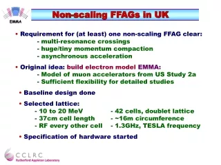
Quick Guide to Fixed-Fielding Alternating Gradient FFAGs • Simplest Dynamical Definition: • FFAG is ~ a cyclotron with a gradient; beam confinement is via: • Strong alternating-gradient (AG) focusing, both planes: radial sector FFAG • normal/reversed gradients alternate (like a synchrotron) • Gradient focusing in horizontal, edge focusing in vertical: spiral sector FFAG • vertical envelope control is through edge focusing (like a cyclotron) • the normal gradient increases edge focusing with radius /momentum (unlike a cyclotron) • A cyclotron can be considered a class of FFAGs • Types of FFAGs: • Scaling: • B field follows a scaling law as a function of radius - rk (k a constant;) present-day scaling FFAGs: Y. Mori, Kyoto University Research Reactor Institute • Nonscaling: • Linear (quadrupole) gradient; beam parameters generally vary with energy (EMMA FFAG, Daresbury Laboratory, first nonscaling FFAG) • Nonlinear-gradient; beam parameters such as machine tune can be fixed (as in a synchrotron, examples: PAMELA and a new generation of nonscaling, constant-tune CW FFAGs)
Thin lens transverse focusing terms • The FFAG combines all forms of transverse beam (envelope) confinement in an arbitrary CF magnet: • For the horizontal, the three terms are • For the vertical only the quadrupole gradient, kDl, and the edge term are available • The different focusing terms can be varied independently to optimize machine parameters such as footprint, aperture, and tune in a FFAG synchrotron cyclotron
More on gradient/edge-focusing • Understanding the powerful interplay between gradient and edge focusing is critical to understanding the potential of FFAGs • In cyclotrons, • horizontal envelope control is through the centripetal term • Centripetal term increases with radius/pathlength/momentum in the cyclotron magnets • Vertical envelope control is through edge focusing / field shaping at the magnet edges • proportional to the constant dipole field; more difficult to increase, much weaker than horizontal focusing in cyclotrons • In FFAGs, • the gradient increases both the horizontal (centripetal) and vertical (edge focusing) with radius/momentum • This last point is very important for FFAGs because it allows the field, orbit location, and important machine parameters such as tune to be more independent and strongly controlled than in cyclotrons
To summarize beam envelope control (in the thin Lens Limit): • Centripetal (Cyclotrons + FFAGs) : • bend plane only, horizontally defocusing or focusing • Strength (bend angle/bend radius of dipole field component on reference orbit) • Edge focusing (Cyclotrons + FFAGs) : • Horizontally focusing / vertically defocusing, vice versa, or no focusing depending on field at entrance and entrance angle • Strength tan , (or ~ for reasonably small edge-crossing angles) • Gradient focusing (Synchrotrons + FFAGs) : • Body gradient, fields components > dipole: B= a + bx +cx2 + dx3 + …B’= b + 2cx + 3dx2 + … • Linear field expansion, constant gradient • Synchrotrons + linear-field nonscaling FFAGs (muon accelerators) • Nonlinear field expansion up to order k, magnitude of gradient increases with r or energy: • Scaling FFAGs • Arbitrary nonlinear field expansion, magnitude of gradient increases with r or energy: • Nonlinear Non-scaling FFAGs Edge crossing angles are kept deliberately small in large multi-cell synchrotron rings. This term becomes increasingly important for and causes problems in small synchrotron rings.
More on the role of the gradient in edge-focusing • Understanding the powerful interplay between gradient and edge focusing is critical to understanding the potential of FFAGs • In cyclotrons, • horizontal envelope control is through the centripetal term • Centripetal term increases with radius/pathlength/momentum in the cyclotron magnets • Vertical envelope control is through edge focusing / field shaping at the magnet edges • proportional to the constant dipole field; more difficult to increase, much weaker than horizontal focusing in cyclotrons • In FFAGs, • the gradient increases both the horizontal (centripetal) and vertical (edge focusing) with radius/momentum • This last point is very important for FFAGs because it allows the field, orbit location, and important machine parameters such as tune to be more independent and strongly controlled than in cyclotrons
Evolution of the FFAG Scaling FFAGs (spiral or radial-sector) are characterized by geometrically similar orbits of increasing radius, imposing a constant tune (field and derivative gradient scale identically with r). Magnetic field follows the law B rk, with r as the radius, and k as the constant field index. Spiral Sector: example: more compact; positive bend field only. Vertical focusing controlled by edge crossing angle. Field expansion: k determines multipole order; Comments: the lower the k value, the more slowly field increases with r and the larger the horizontal aperture, but the more linear the field composition and dynamics. Radial Sector: example: This is a triplet DFD cell; there are also FDF, FODO and doublets. In a radial sector the D is the negative of the F field profile, but shorter. F D D
Extraction reference orbit Injection reference orbit Linear nonscaling FFAGs for rapid acceleration Linear-field, nonscaling FFAGs. Ultra-compact magnet aperture, proposed and developed for High Energy Physics (Neutrino Factories and Muon Colliders), relaxes optical parameters and aims only for stable acceleration. In general they are not suitable for an accelerator with a modest acceleration system and accelerate only over a factor of 2-3 range in momentum. EMMA – world’s first nonscaling FFAG, @Daresbury Laboratory, NOW ACCELERATING BEAM !!!!! D F F Characteristics– tune sweep/unit cell, parabolic pathlength on momentum (small radial apertures); serpentine (rapid) acceleration – beam “phase-slips”, crossing the peak 3 times, accelerating between rf buckets Cartoon of orbit compaction: nonsimilar orbits, nonconstant tune, resonance crossing
Extraction reference orbit 40cm ~17cm Injection reference orbit Tune-stable nonscaling FFAGs for slow acceleration Two lattice approaches • Machida version - which uses a scaling law truncated at decapole, rectangular magnets , (not discussed here, see PAMELA project) and • Johnstone version – The most general form of a radial sector : allowing independent, unconstrained field and edge profiles between two combined-function magnets. Tune-stable, nonscaling FFAGs Tuneis strongest indicator of stableparticle motion – allowing particles execute periodic motion eventually returning to the same transverse position relative to a reference orbit. Constraining the tune can be sufficient to design a stable machine. Release of other linear optical parameter allows flexibility and optimization both in cost and complexity of the accelerator design;i.e. simpler magnets, strong vertical focusing, for example Tune Stable Nonscaling FFAGs have either linear or nonlinear field profiles and/or edge contours 1 2
Progression of the NS FFAG Design • Linear (constant gradient) • Rectangular magnets EMMA machine at Daresbury Laboratory • Non-constant machine tune, significant investment in high-power rf • EMMA has 19 rf cavities in a 42-cell ring. • Maximum acceleration range: factor of 4 (practically 2-3) • Linear (constant) gradient + edge contour • Edge contour on magnets to stabilize tune • Increase of momentum range to a factor of 6 • Nonlinear gradient + edge contour • Arbitrary order combined with magnet edge contour • Stable tune • Slow acceleration supported - low-power, but swept-frequency rf system • Increase of momentum range as high as 44 in a more compact footprint • Nonlinear gradient – isochronous • Stable tune • Gradient/magnet shape adjusted for isochronous orbits - simple low-power fixed-frequency rf system
The Next Generation of FFAGs – Applying a Nonlinear Gradient to the Nonscaling FFAG • Compact machines; i.e. footprint, aperture and tune control required higher-order, tailored field profiles • An arbitrary field expansion has been exceptionally successful • Order of magnitude increase in momentum range over initial NS concept • an acceleration range of a factor of 44 has been achieved. • Large Dynamic Acceptance in predominately nonlinear fields • Strong focusing, 90 cell tunes (or higher) achieved in both horizontal and vertical well into the relativistic regime • Isochronous orbits have been achieved in a nonscaling FFAG by applying an nonlinear gradient and edge contour • Isochronous implies CW operation and simple rf systems
The significance of CW Accelerators • A CW accelerator implies: • Fixed magnetic fields • 50 Hz is the ~ practical technical limit for pulsed magnet systems • Stored power and expense of pulsed supplies can be commercially prohibitive • The simplicity of fixed-frequency rf • the rotational frequency of orbits is a constant at all energies • Consequences of non-isochronous orbits • Beam is pulsed at the rf sweep rate, not continuous • Swept-frequency rf (rf timing is changed to match the revolution time of the beam – the synchrotron and synchro-cyclotron) • 50-100 Hz sweep rate for rf frequencies ≥ tens of MHz • KHz sweep rate for broad-band rf (~MHz) • slow acceleration, high power consumption
Relativistic Isochronous NS FFAGs - • NS FFAG can maintain isochronous orbits at relativistic energies • Pathlength of isochronous orbits are proportional to velocity • Orbits as a function of momentum follow the B field, therefore the B field must scale with velocity • At relativistic energies, momentum is an increasingly nonlinear function of velocity; therefore B field transitions from a linear slope to nonlinear, non-relativistic to relativistic as an approximate function of radius. • THIS HAS BEEN ACHIEVED IN RECENT NONLINEAR NS FFAG DESIGNS • Nonlinear field expansion + edge angle can constrain the tune • Nonlinear gradient provides very strong focusing at high energy in both planes relative to the cyclotron FFAG limit ≥2 GeV protons Cyclotron limit ~ 1 GeV protons P (MeV/c) or Bfield or normalized pathlength
The Isochronous Condition • Dipole fields, i.e. cyclotrons, maintain isochronicity at nonrelativistic energies - that is, at nonrelatistic energies velocity is proportional to momentum and path length is proportional to momentum in a constant B field, therefore path length is proportional to velocity. • Isochronism can be imposed on the orbits in FFAGs into nonrelativistic energies by requiring the path length remain proportional to velocity, which has an increasingly nonlinear dependence on momentum. The average B field which determines path length as a function of momentum must increase nonlinearly in this energy regime according to: *Note that in the nonrelativistic regime, injcan be <<ext and aperture machine radius, at relativistic energies, aperture << machine radius
Summary of Nonscaling FFAG properties • By utilizing all conventional modes of transverse focusing for beam and machine parameter control the FFAG can be a powerful hybrid of the cyclotron and synchrotron • The FFAG has the potential to combine the best features of the synchrotron and cyclotron • Strong focusing allows synchrotron-like straights – and therefore the low losses associated with synchrotrons especially at extraction • Variable energy extraction – elimination of degraders (to be discussed further) • The simplicity of fixed magnetic fields rather than pulsed operation • Very recently - the simplicity of fixed-frequency rather than swept-frequency rf systems; producing reliable, continuous, cyclotron-like beam • The low operational overhead and simplicity of the cyclotron
Advanced design and simulation of anIsochronous 250-1000 MeVNonscaling FFAG 2m General Parameters of an initial 0. 250 – 1 GeV non-scaling, near-isochronous FFAG lattice design Clockwise: Matematica: Ring tune, deviation from isochronous orbit (%), and radius vs. momentum • Comments and further work • Tracking results indicate ~400 mm-mr; relatively insensitive to errors • Low losses
Advanced ModelingSimulations in COSY INFINITY • In general accelerator codes provide too-little flexibility in field description and are limited to low order in the dynamics, new tools were developed for the study and analysis of FFAG dynamics based on transfer map techniques unique to the code COSY INFINITY. HARD EDGE • Various methods of describing complex fields and components are now supported including representation in radius-dependent Fourier modes, complex magnet edge contours, as well as the capability to interject calculated or measured field data from a magnet design code or actual components. FULL FRINGE FIELDS Arbitrary shapes, field content, contours Other FFAG codes: ZGOUBI, F. Meot, some implementation in CYCLOPS (Baartman, TRIUMF)
Example of dynamics studies of fixed-field accelerators using new tools in COSY • Below is a sample FFAG having sixfold symmetry, with focusing stemming from an azimuthal field variation expressed as a single Fourier mode as well as edge focusing. The system is studied to various orders of out-of-plane expansion with the results for orders three and five shown below (typical of a conventional out-of-plane expansion in codes like Cyclops). Tracking in a model non-scaling six-fold symmetric FFAG for horizontal (left pairs) and vertical (right, pairs) with 3rd (top), 5th(middle), and 11th-order (bottom) out of plane expansion, with focusing from an azimuthal field variation expressed as a single Fourier mode as well as edge focusing . With (left) and without (right) Expo symplectification is shown.
Comparison of a sector cyclotron with a FFAG using advanced design and simulation tools • Study of a low-energy cyclotron vs. FFAG equivalent designs: • 5 kG field at injection; (For cyclotron implies a 5 kG field at all energies.) • 1T limit on the extraction field in the FFAG • ≥10 cm magnet @injection (to achieve 5 kG) • ≤5 cm between magnets at injection. • Same footprint: an ~0.9 m radius • No reverse bends in the FFAG • vertical focusing is through edge crossing. • 4 sectors both designs 0.5 T field Low-energy cyclotron (left) and equivalent FFAG (right) Subtleties in transverse dynamics of cyclotron and FFAG at 100 keV: Horizontal cyclotron and FFAG (left pair) and vertical cyclotron and FFAG (right pair) as observed in advanced simulations
Field Map and Tracking: 250-1000 MeV Proton Driver: Order 11 • Immediate large DA aperture: • +/- 0.25 m horizontal • Larger than vertical gap of magnet • 50-100 mm-mr without correction • 0.1-1% error tolerance –typical magnet tolerances • Final isochronous optimization will be performed using advanced optimizers in COSY Dynamic aperture at 250, 585, and1000 MeV – step size is 1.5 cm in the horizontal (left) and 1 mm in the vertical (right).
1-GeV Proton Driver Modeled in CYCLOPS: fine mesh and fringe fields (Y.N Ray and M. Craddock, TRIUMF) • B field with Enge function fall off • tune per cell (radial, horizontal) • tune/cell (z, vertical) • frequency change, isochronous to +/- 3% using simple hard-edge model: progress will require the advanced codes; agrees with COSY results
Very Preliminary Hardware Concepts for a SC Nonlinear NS FFAG (ADS application) • An innovative new approach to a combined-function 4T magnet is under design based conventional NbTi superconducting magnet technology and construction techniques. • Preliminary rf parameters have been investigated With a small vertical aperture of only a few cm, the large horizontal magnet apertures do not present a serious technical issue in terms of an rf structure.
Application: Accelerator-Driven Subcritical ReactorCW beam is a requirement + duplication of accelerator for reliability • Advantages • Injection through a lower-energy H- ring • CW operation for high power output • Compact footprint (especially compared to a 1 GeVlinac) • The simplicity of fixed-frequency rf system • Swept-frequency rf is required for a synchrotron or synchro-cyclotron • Isochronous cyclotron is large machine • Low losses • With strong focusing losses are comparable to a synchrotron • Critical for successful high-intensity operation (10 MW) • Strong focusing – strong vertical tunes • Mitigate impact of space charge • Promote increased stability at high intensities
Summary of advantages based on advances in FFAG technology • CW operation (into relativistic energies) with new isochronous lattices • Simplicity and lower cost of fixed-frequency rf • Strong focusing in a fixed field accelerator has demonstrated • Large, stable dynamical acceptance • Lower losses, particularly with smaller beam envelopes in vertical • Support of multiple long straights • Lowered extraction losses • Mitigation of space charge effects (strong tune in vertical), higher bunch intensities • Resonant and kicker-based extraction (horizontal and vertical) • Variable energy without use or reduced use of a degrader • Improved beam transmission at low energies • Respiration gating can be kicker based • Reduced shielding requirements – reduced civil costs • Nested Rings • Compact footprint even for a multi-ion facility Presently developing 3-8 GeV frequency-swept FFAGs (scaling and nonscaling) for the 2nd stage of acceleration for Project X (in collaboration with Imperial College, Fermilab, MSU, and ASTeC).
FFAGs for Hadron TherapyAre these Advantages Sufficient to Warrant a NEW type of Ion Beam Therapy Facility? • Given the technical advances on conventional accelerator facilities, the impact of FFAGs on proton cancer therapy is unlikely!!! • One of the strongest arguments for the prevailing dominance of cyclotrons is continuous (CW) beam. One paper which makes this specific case is: “Fast Scanning Techniques for Cancer Therapy with Hadrons – A Domain of Cyclotrons” J.M. Schippers, D. Meer, E. Pedroni, Proceedings of CYCLOTRONS 2010, Lanzhou, China The Conclusion: “In order to exploit the advantages of 3D pencil beam scanning, the scanning process must be performed as fast as possible. This allows different strategies to prevent dose errors due to tumour/organ motion. A reliable application of fast 3D scanning necessitates firm specifications on the accelerator: a CW beam, with an intensity that must be stable, quickly and accurately adjustable over a large dynamic range as well as a fast and accurate energy modulation. Currently the combination of these specifications is not possible to achieve with pulsed machine operation at repetition rates below 0.5-1 kHz.” One can only employ broad band, (~MHz) RF, to attain these repetition rates (PAMELA)
Dual Accelerator Patient Model (PSI data*) Below is a model-based treatment using 70 MeV as the lower limit since many nozzles ( or energy degraders) only work in the 70 to 250 MeV range. (Lower energies can be obtained by plastic range shifters placed close to the skin and aperture, for example with breast, pediatric patients, and parotid tumors in the jaw. ) • Site Percentage Energy Range (MeV) • Lung 9% 70 - 170 • Breast 3% 70 - 140 • CNS 15% 70 - 150 ( central nervous system, i.e., base of skull & tumors around spinal vertebrae) • Rectum 2% 70- 170 ( also cervical cancers may be a few % in this energy range) • Pediatric 8% 70 - 150 • Head & Neck 15% 70 - 150 • Prostate 45% 200-250 • Other 2% This fits nicely with a dual energy accelerator system where E≤150 MeV can be used for roughly 50% of the patients. At PSI all patients were treated with E< 180 MeV excluding prostates. * *based on discussions with G. Coutrakon, 2009.
Two-Stage Proton Therapy Facility • Dual Accelerator Model: • Simultaneous treatment/setup can be conveniently split into 70-150 MeV, 150-250 MeV • Accelerator is a small part of the cost of a facility • Delivery beamlines are also a drop in the bucket • Could consider separate gantries: gantries with smaller energy range requirements are conceivably cheaper – easier magnets; lower energy gantry much smaller. • Dual accelerators are facilitated using FFAGs by • Multiple long straights • Ease of injection/extraction • CW operation in both stages
CW 18-150 MeV H- (p + 2e) NS FFAG Stripping wire H- proton for a low energy treatment beam • Comments and further work • Peak field 0.8T @extraction in F - can take this design to 180 MeV • Increase compactness: 3-sector or no reverse bends, low losses – reduced shielding • Extraction at 150 MeV through field shaping of high-energy orbit Tune per cell and ring tune. Extended fringe field will split tunes Average radius vs momentum and deviation in % from isochronous average radius
Example: lower-energy isochronous FFAG –preliminary 150-250 MeV SC Proton Ring • Comments • Peak field 3.5T @extraction in F; • small 25 cm aperture • Low losses Ring tune
What about Carbon Therapy? • Cyclotron • Not CW at 400 MeV/, the energy required for therapy • IBA SC synchro-cyclotron operates @100 Hz • Requires a degrader • Synchrotron • Large footprint (10m radius, Hitachi) • Low duty cycle • High operational overhead • FFAG • 1.2 GeV ~ 400 MeV/ • A CW, small foot print (5m radius) design proposed for ADS will accelerate C6+ , or any charge/mass ratio of 1/2
1 GeV CW FFAG for Carbon Therapy 2m General Parameters of an initial 0. 250 – 1 GeV non-scaling, near-isochronous FFAG lattice design Clockwise: ZGOUBI deviation from isochronous orbit (%), CYCLOPS: tunes and deviation from isochronous, and bottom: ZGOUBI cell tunes • Comments and further work • Tracking results indicate ~400 mm-mr; relatively insensitive to errors • Losses and space charge • Advanced optimization to improve isochronous operation • EXTRACTION
Summary of Operational Advantages in a Dual Stage FFAG Proton Therapy Facility CW operation with …. • Variable energy • Limited use of degraders if needed; 250 – 150; or 150 – 70 MeV. • Low loss operation, comparable to synchrotrons • Multi- accelerators/multi-room operation is perhaps the most important next step in patient throughput. • Less susceptible to hysteresis, smaller tuning window • Less susceptible to energy variations in beam phase space • Amenable to most advanced hardware developments in cyclotrons and synchrotrons • Much of the ground-breaking work in PAMELA can be adapted (the higher energy ring, for example uses up to octupole field expansion) • FFAG is ideal for CARBON THERAPY and Proton Radiography
SUMMARY • Nonlinear NS FFAGs • Advancing very rapidly • Large DA aperture despite strong nonlinearities • CW operation appears feasible to GeV energies • Most promising applications • ADS and ATW • Carbon hadron therapy • Homeland security (cargo scanning) • Proton Computed Tomography (>300 MeV protons) • 1 GeV machine under conceptual design MOST IMPORTANT WE NEED A NAME FOR THE 1 GEV MACHINE!!