Download
1 / 21
540 likes | 1.82k Views
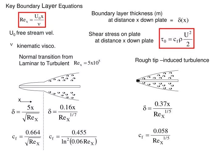
Key Boundary Layer Equations. Boundary layer thickness (m) at distance x down plate =. U 0 free stream vel. kinematic visco. Shear stress on plate at distance x down plate. n. Normal transition from Laminar to Turbulent . Rough tip –induced turbulence. x.

E N D
Key Boundary Layer Equations Boundary layer thickness (m) at distance x down plate = U0 free stream vel. kinematic visco. Shear stress on plate at distance x down plate n Normal transition from Laminar to Turbulent Rough tip –induced turbulence x
Shear Resistance due to flow of a viscous fluid of density r and free stream vel = Uo Over a plate Length L Breath B
Flow in Conduits --Pipes - + Head IN from pump Note pump power Heat Loss Head OUT from Turbine Note power recovered Q discharge 0< h <1 efficiency Our concern is to calculate this term
We use energy Eq.—assume a = 1 (1) If we select the points [a] and [b] to be at the top of the tanks Eq. 1 Simplifies to We can not measure H BUT we can estimate the head loss hL
There are a number of items that contribute to the head loss hL
Minor Losses In Example problem Note form Dimensionless No X V2/2g
Head loss in a pipe In this case reduces to
Head loss in a pipe (1) =0 by continuity Wetted perimeter Rearrange (2) (1) And (2)
Head loss in a pipe Introduce a Dimensionless friction factor Then In a full circular pipe So to find head loss hL Need to find friction factor f