Download
1 / 17
240 likes | 464 Views
Boundary layer concept. Laminar flow. Laminar Boundary Layer Flow. The laminar boundary layer is a very smooth flow, while the turbulent boundary layer contains swirls or “eddies.” The laminar flow creates less skin friction drag than the turbulent flow, but is less stable.

E N D
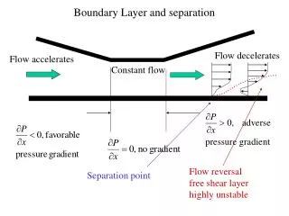
Laminar Boundary Layer Flow • The laminar boundary layer is a very smooth flow, while the turbulent boundary layer contains swirls or “eddies.” • The laminar flow creates less skin friction drag than the turbulent flow, but is less stable. • Boundary layer flow over a wing surface begins as a smooth laminar flow. As the flow continues back from the leading edge, the laminar boundary layer increases in thickness.
Turbulent Boundary Layer Flow • At some distance back from the leading edge, the smooth laminar flow breaks down and transitions to a turbulent flow. • From a drag standpoint, it is advisable to have the transition from laminar to turbulent flow as far aft on the wing as possible, or have a large amount of the wing surface within the laminar portion of the boundary layer. • The low energy laminar flow, however, tends to break down more suddenly than the turbulent layer.
Pipes in series is defined as the pipes of different lengths and different diameters connected end to end to form a pipe line. L1,L2,L3 = length of pipes 1,2 and 3 d1,d2,d3 = diameter of pipes 1,2,3 v1,v2,v3= velocity of flow through pipes 1,2,3 f1,f2,f3 = coefficient of frictions for pipes 1,2,3 H = difference of water level in the two tanks The discharge passing through the pipe is same. Q=A1V1=A2V2=A3V3 • The difference in liquid surface levels is equal to the sum of the total head loss in the pipes
Parallel pipe system • Consider a main pipe which divide into two or more branches as shown in figure Again join together downstream to form a single pipe then the branch pipes are said to be connected in parallel. The discharge through the main is increased by connecting pipes in parallel the rate of flow in the main pipe is equal to the sum of rate of flow through branch pipes. hence Q =Q1+Q2
In this arrangement loss of head for each pipe is same Loss of head for branch pipe1=loss of head for branch pipe 2
Moody diagram Moody Diagram that can be used to estimate friction coefficients • The Moody friction factor - λ (or f) - is used in the Darcy-Weisbach major loss equation • If the flow is transient - 2300 < Re < 4000 - the flow varies between laminar and turbulent flow and the friction coefficient is not possible to determine. • The friction factor can usually be interpolated between the laminar value at Re = 2300 and the turbulent value at Re = 4000
Total energy gradient line is equal to sum of pressure head ,velocity head and datum head EL = H = p / W + v2 / 2 g + h = constant along a streamline where (EL ) Energy Line • For a fluid flow without any losses due to friction (major losses) or components (minor losses) - the energy line would be at a constant level. In a practical world the energy line decreases along the flow due to losses. • A turbine in the flow reduces the energy line and a pump or fan in the line increases the energy line
Hydraulic Grade Line (HGL ) • Hydraulic gradient line is the sum of pressure head and datum head HGL = p / W + h where The hydraulic grade line lies one velocity head below the energy line.