Download
1 / 62
760 likes | 1.09k Views
Inductors. OBJECTIVES. Become familiar with the basic construction of an inductor, the factors that affect the strength of the magnetic field established by the element.

E N D
OBJECTIVES • Become familiar with the basic construction of an inductor, the factors that affect the strength of the magnetic field established by the element. • Be able to determine the transient (time-varying) response of an inductive network and plot the resulting voltages and currents. • Understand the impact of combining inductors in series or parallel.
INTRODUCTION • In many ways, the inductor is the dual of the capacitor; that is, the voltage of one is applicable to the current of the other, and vice versa. • Like the capacitor, the inductor exhibits its true characteristics only when a change in voltage or current is made in the network.
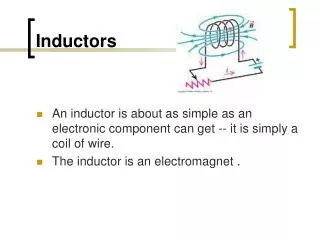
MAGNETIC FIELD • A magnetic field (represented by concentric magnetic flux lines) is present around every wire that carries an electric current. • The direction of the magnetic flux lines can be found simply by placing the thumb of the right hand in the direction of conventional current flow and noting the direction of the fingers.
FIG. 11.13 Defining the flux density B. FIG. 11.10 Determining the direction of flux for an electromagnet: (a) method; (b) notation. FIG. 11.3 Flux distribution for two adjacent, like poles. MAGNETIC FIELD
MAGNETIC FIELD • In the SI system of units, magnetic flux is measured in webers (Wb) as derived from the surname of Wilhelm Eduard Weber. • The applied symbol is the capital Greek letter phi, Φ. • The number of flux lines per unit area, called the flux density, is denoted by the capital letter B and is measured in teslas (T) to honor the efforts of Nikola Tesla.
MAGNETIC FIELD • The flux density of an electromagnet is directly related to the number of turns of, and current through, the coil. • The product of the two, called the magnetomotive force, is measured in ampere-turns (At) as defined by:
FIG. 11.14 Milligaussmeter. MAGNETIC FIELD
FIG. 11.16 Defining the parameters for Eq. (11.6). INDUCTANCE • In total, therefore, inductors are designed to set up a strong magnetic field linking the unit, whereas capacitors are designed to set up a strong electric field between the plates.
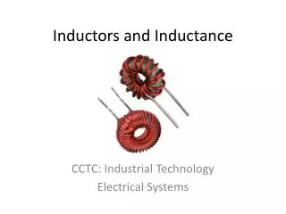
INDUCTANCEInductor Construction • It is also sensitive to the number of turns of wire in the coil as dictated by the following equation and defined in Fig. 11.16 for two of the most popular shapes:
FIG. 11.18 Air-core coil for Example 11.1. INDUCTANCEInductor Construction
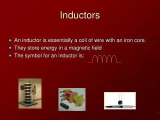
FIG. 11.20 Inductor (coil) symbols. INDUCTANCETypes of Inductors
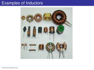
FIG. 11.21 Relative sizes of different types of inductors: (a) toroid, high-current; (b) phenolic (resin or plastic core); (c) ferrite core. INDUCTANCETypes of Inductors
FIG. 11.23 Variable inductors with a typical range of values from 1 mH to 100 mH; commonly used in oscillators and various RF circuits such as CB transceivers, televisions, and radios. INDUCTANCETypes of Inductors
FIG. 11.25 Practical equivalent model for an inductor. FIG. 11.24 Complete equivalent model for an inductor. INDUCTANCEPractical Equivalent Inductors
FIG. 11.27 Digital reading inductance meter. (Courtesy of B+K Precision.) INDUCTANCEMeasurement and Testing of Inductors
FIG. 11.28 Generating an induced voltage by moving a conductor through a magnetic field. INDUCED VOLTAGE vL • Faraday’s law of electromagnetic induction.
FIG. 11.29 Demonstrating Faraday’s law. INDUCED VOLTAGE vL
R-L TRANSIENTS: THE STORAGE PHASE • A great number of similarities exist between the analyses of inductive and capacitive networks. • That is, what is true for the voltage of a capacitor is also true for the current of an inductor, and what is true for the current of a capacitor can be matched in many ways by the voltage of an inductor.
FIG. 11.31 Basic R-L transient network. R-L TRANSIENTS: THE STORAGE PHASE
FIG. 11.32 iL, yL, and yR for the circuit in Fig. 11.31 following the closing of the switch. R-L TRANSIENTS: THE STORAGE PHASE
FIG. 11.33 Effect of L on the shape of the iL storage waveform. R-L TRANSIENTS: THE STORAGE PHASE
FIG. 11.34 Circuit in Figure 11.31 the instant the switch is closed. R-L TRANSIENTS: THE STORAGE PHASE
FIG. 11.36 Series R-L circuit for Example 11.3. FIG. 11.35 Circuit in Fig. 11.31 under steady-state conditions. R-L TRANSIENTS: THE STORAGE PHASE
R-L TRANSIENTS: THE STORAGE PHASE FIG. 11.37 iL and vL for the network in Fig. 11.36.
INITIAL CONDITIONS • Since the current through a coil cannot change instantaneously, the current through a coil begins the transient phase at the initial value established by the network (note Fig. 11.38) before the switch was closed. • It then passes through the transient phase until it reaches the steady-state (or final) level after about five time constants. • The steadystate level of the inductor current can be found by substituting its shortcircuit equivalent (or Rlfor the practical equivalent) and finding the resulting current through the element.
FIG. 11.38 Defining the three phases of a transient waveform. INITIAL CONDITIONS
FIG. 11.39 Example 11.4. INITIAL CONDITIONS
FIG. 11.40 iL and vL for the network in Fig. 11.39. INITIAL CONDITIONS
FIG. 11.41 Demonstrating the effect of opening a switch in series with an inductor with a steady-state current. R-L TRANSIENTS: THE RELEASE PHASE
FIG. 11.42 Initiating the storage phase for an inductor by closing the switch. R-L TRANSIENTS: THE RELEASE PHASE
FIG. 11.43 Network in Fig. 11.42 the instant the switch is opened. R-L TRANSIENTS: THE RELEASE PHASE
FIG. 11.45 The various voltages and the current for the network in Fig. 11.44. R-L TRANSIENTS: THE RELEASE PHASE
FIG. 11.46 Example 11.6. THÉVENIN EQUIVALENT: t =L/RTh
FIG. 11.47 Determining RTh for the network in Fig. 11.46. THÉVENIN EQUIVALENT: t =L/RTh
FIG. 11.48 Determining ETh for the network in Fig. 11.46. THÉVENIN EQUIVALENT: t =L/RTh
FIG. 11.49 The resulting Thévenin equivalent circuit for the network in Fig. 11.46. THÉVENIN EQUIVALENT: t =L/RTh
FIG. 11.50 The resulting waveforms for iL and vL for the network in Fig. 11.46. THÉVENIN EQUIVALENT: t =L/RTh
FIG. 11.51 Example 11.7. THÉVENIN EQUIVALENT: t =L/RTh
FIG. 11.52 Thévenin equivalent circuit for the network in Fig. 11.51 for t ≥ 0 s. THÉVENIN EQUIVALENT: t =L/RTh
FIG. 11.53 The current iL for the network in Fig. 11.51. THÉVENIN EQUIVALENT: t =L/RTh
INSTANTANEOUS VALUES • The development presented in Section 10.8 for capacitive networks can also be applied to R-L networks to determine instantaneous voltages, currents, and time. • The instantaneous values of any voltage or current can be determined by simply inserting t into the equation and using a calculator or table to determine the magnitude of the exponential term.
AVERAGE INDUCED VOLTAGE: vLav • For inductors, the average induced voltage is defined by:
FIG. 11.54 Current iL to be applied to a 4 mH coil in Example 11.8. AVERAGE INDUCED VOLTAGE: vLav
FIG. 11.55 Voltage across a 4 mH coil due to the current in Fig. 11.54. AVERAGE INDUCED VOLTAGE: vLav
FIG. 11.56 Inductors in series. INDUCTORS IN SERIES AND IN PARALLEL
FIG. 11.57 Inductors in parallel. INDUCTORS IN SERIES AND IN PARALLEL
FIG. 11.59 Terminal equivalent of the network in Fig. 11.58. FIG. 11.58 Example 11.9. INDUCTORS IN SERIES AND IN PARALLEL
STEADY-STATE CONDITIONS • We found in Section 11.5 that, an ideal inductor can be replaced by a short-circuit equivalent once steady-state conditions. • Recall that the term steady state implies that the voltage and current levels have reached their final resting value and will no longer change unless a change is made in the applied voltage or circuit configuration.