Download
1 / 18
180 likes | 360 Views
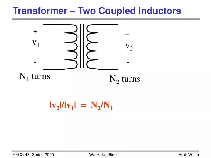
Transformer – Two Coupled Inductors. +. +. v 1. v 2. -. -. N 1 turns. N 2 turns. |v 2 |/|v 1 | = N 2 /N 1. AC Power System. Summary of Electrical Quantities. Summary of Electrical Quantities (concluded). Types of Circuit Excitations and Their Uses.

E N D
Transformer – Two Coupled Inductors + + v1 v2 - - N1 turns N2 turns |v2|/|v1| = N2/N1
Types of Circuit Excitations and Their Uses • Steady excitation (“DC”) – steady DC voltage or • current sources. Uses: the DC part of all kinds • of communications, transistor, sensor, … circuits • Transient excitation -- DC voltage or current sources • are suddenly turned on or off. Uses: flashbulb • circuit where charge a capacitor and suddenly dis- • charge it through flashbulb; put an on and an off • switching together and get a digital pulse: + = • Sinusoidal excitation (“AC”) – Uses: AC power • systems; communication systems to find frequency • response.
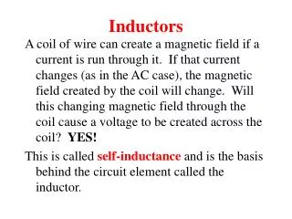
First-Order Circuits • A circuit which contains only sources, resistors and an inductor is called an RL circuit. • A circuit which contains only sources, resistors and a capacitor is called an RC circuit. • RL and RC circuits are called first-order circuits because their voltages and currents are described by first-order differential equations. R R i i vs – + vs – + L C
The natural response of an RL or RC circuit is its behavior (i.e. current and voltage) when stored energy in the inductor or capacitor is released to the resistive part of the network (containing no independent sources). • The step response of an RL or RC circuit is its behavior when a voltage or current source step is applied to the circuit, or immediately after a switch state is changed.
Natural Response of an RL Circuit • Consider the following circuit, for which the switch is closed for t < 0, and then opened at t = 0: Notation: 0– is used to denote the time just prior to switching 0+ is used to denote the time immediately after switching • The current flowing in the inductor at t = 0– is Io t = 0 i + v – Io Ro L R
Solving for the Current (t 0) • For t > 0, the circuit reduces to • Applying KVL to the LR circuit: • Solution: i + v – Io Ro L R
Solving for the Voltage (t > 0) • Note that the voltage changes abruptly: + v – Io Ro L R
Time Constant t • In the example, we found that • Define the time constant • At t = t, the current has reduced to 1/e (~0.37) of its initial value. • At t = 5t, the current has reduced to less than 1% of its initial value.
Transient vs. Steady-State Response • The momentary behavior of a circuit (in response to a change in stimulation) is referred to as its transient response. • The behavior of a circuit a long time (many time constants) after the change in voltage or current is called the steady-state response.
Review (Conceptual) • Any* first-order circuit can be reduced to a Thévenin (or Norton) equivalent connected to either a single equivalent inductor or capacitor. • In steady state, an inductor behaves like a short circuit • In steady state, a capacitor behaves like an open circuit RTh VTh – + ITh RTh L C
Natural Response of an RC Circuit • Consider the following circuit, for which the switch is closed for t < 0, and then opened at t = 0: Notation: 0– is used to denote the time just prior to switching 0+ is used to denote the time immediately after switching • The voltage on the capacitor at t = 0– is Vo t = 0 Ro + v – + Vo R C
Solving for the Voltage (t 0) • For t > 0, the circuit reduces to • Applying KCL to the RC circuit: • Solution: i + v – Ro + Vo C R
Solving for the Current (t > 0) • Note that the current changes abruptly: i + v – Ro + Vo C R
Time Constant t • In the example, we found that • Define the time constant • At t = t, the voltage has reduced to 1/e (~0.37) of its initial value. • At t = 5t, the voltage has reduced to less than 1% of its initial value.
RL Circuit Inductor current cannot change instantaneously time constant RC Circuit Capacitor voltage cannot change instantaneously time constant Natural Response Summary i + v – L R C R