Download

1 / 92
970 likes | 1.26k Views
Inductors. OBJECTIVES. Become familiar with the basic construction of an inductor, the factors that affect the strength of the magnetic field established by the element, and how to read the nameplate data.

E N D
OBJECTIVES • Become familiar with the basic construction of an inductor, the factors that affect the strength of the magnetic field established by the element, and how to read the nameplate data. • Be able to determine the transient (time-varying) response of an inductive network and plot the resulting voltages and currents. • Understand the impact of combining inductors in series or parallel. • Develop some familiarity with the use of PSpice or Multisim to analyze networks with inductive elements.
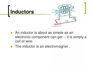
INTRODUCTION • Three basic components appear in the majority of electrical/electronic systems in use today. • They include the resistor and the capacitor, which have already been introduced, and the inductor.
INTRODUCTION • In many ways, the inductor is the dual of the capacitor; that is, the voltage of one is applicable to the current of the other, and vice versa. • Like the capacitor, the inductor exhibits its true characteristics only when a change in voltage or current is made in the network.
MAGNETIC FIELD • Magnetism plays an integral part in almost every electrical device used today in industry, research, or the home. • Generators, motors, transformers, circuit breakers, televisions, computers, tape recorders, and telephones all employ magnetic effects to perform a variety of important tasks.
FIG. 11.1 Flux distribution for a permanent magnet. FIG. 11.2 Flux distribution for two adjacent, opposite poles. MAGNETIC FIELD
FIG. 11.3 Flux distribution for two adjacent, like poles. FIG. 11.4 Effect of a ferromagnetic sample on the flux distribution of a permanent magnet. MAGNETIC FIELD
FIG. 11.5 Effect of a magnetic shield on the flux distribution. MAGNETIC FIELD
MAGNETIC FIELD • A magnetic field (represented by concentric magnetic flux lines, as in Fig. 11.6) is present around every wire that carries an electric current. • The direction of the magnetic flux lines can be found simply by placing the thumb of the right hand in the direction of conventional current flow and noting the direction of the fingers.
FIG. 11.6 Magnetic flux lines around a current-carrying conductor. FIG. 11.7 Flux distribution of a single-turn coil. MAGNETIC FIELD
FIG. 11.9 Electromagnet. FIG. 11.8 Flux distribution of a current-carrying coil. MAGNETIC FIELD
FIG. 11.10 Determining the direction of flux for an electromagnet: (a) method; (b) notation. MAGNETIC FIELD
FIG. 11.13 Defining the flux density B. MAGNETIC FIELD
MAGNETIC FIELD • In the SI system of units, magnetic flux is measured in webers (Wb) as derived from the surname of Wilhelm Eduard Weber (Fig. 11.11). • The applied symbol is the capital Greek letter phi, Φ. • The number of flux lines per unit area, called the flux density, is denoted by the capital letter B and is measured in teslas (T) to honor the efforts of Nikola Tesla, a scientist of the late 1800s
MAGNETIC FIELD • In equation form:
MAGNETIC FIELD • In Eq. (11.1), the equivalence is given by:
MAGNETIC FIELD • The flux density of an electromagnet is directly related to the number of turns of, and current through, the coil. • The product of the two, called the magnetomotive force, is measured in ampere-turns (At) as defined by:
FIG. 11.14 Milligaussmeter. MAGNETIC FIELD
FIG. 11.15 Some areas of application of magnetic effects. MAGNETIC FIELD
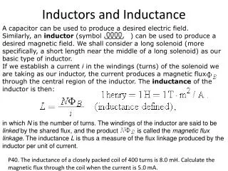
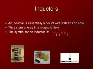
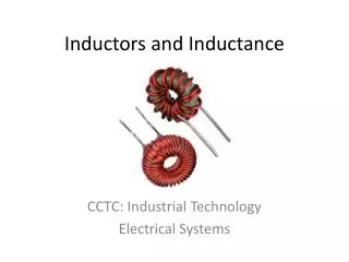
INDUCTANCE • In the previous section, we learned that sending a current through a coil of wire, with or without a core, establishes a magnetic field through and surrounding the unit. • This component, of rather simple construction (see Fig. 11.16), is called an inductor (often referred to as a coil). • Its inductance level determines the strength of the magnetic field around the coil due to an applied current. • The higher the inductance level, the greater is the strength of the magnetic field.
FIG. 11.16 Defining the parameters for Eq. (11.6). INDUCTANCE • In total, therefore, inductors are designed to set up a strong magnetic field linking the unit, whereas capacitors are designed to set up a strong electric field between the plates.
INDUCTANCEInductor Construction • In Chapter 10, we found that capacitance is sensitive to the area of the plates, the distance between the plates, and the dielectic employed. • The level of inductance has similar construction sensitivities in that it is dependent on the area within the coil, the length of the unit, and the permeability of the core material.
INDUCTANCEInductor Construction • It is also sensitive to the number of turns of wire in the coil as dictated by the following equation and defined in Fig. 11.16 for two of the most popular shapes:
FIG. 11.18 Air-core coil for Example 11.1. INDUCTANCEInductor Construction
FIG. 11.19 Inductors for Example 11.2. INDUCTANCEInductor Construction
INDUCTANCETypes of Inductors • Inductors, like capacitors and resistors, can be categorized under the general headings fixed or variable. • The symbol for a fixed air-core inductor is provided in Fig. 11.20(a), for an inductor with a ferromagnetic core in Fig. 11.20(b), for a tapped coil in Fig. 11.20(c), and for a variable inductor in Fig. 11.20(d).
FIG. 11.20 Inductor (coil) symbols. INDUCTANCETypes of Inductors
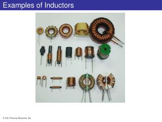
INDUCTANCETypes of Inductors • Fixed • Fixed-type inductors come in all shapes and sizes. • However, in general, the size of an inductor is determined primarily by the type of construction, the core used, and the current rating.
FIG. 11.21 Relative sizes of different types of inductors: (a) toroid, high-current; (b) phenolic (resin or plastic core); (c) ferrite core. INDUCTANCETypes of Inductors
FIG. 11.22 Typical areas of application for inductive elements. INDUCTANCETypes of Inductors
INDUCTANCETypes of Inductors • Variable • A number of variable inductors are depicted in Fig. 11.23. • In each case, the inductance is changed by turning the slot at the end of the core to move it in and out of the unit. • The farther in the core is, the more the ferromagnetic material is part of the magnetic circuit, and the higher is the magnetic field strength and the inductance level.
FIG. 11.23 Variable inductors with a typical range of values from 1 mH to 100 mH; commonly used in oscillators and various RF circuits such as CB transceivers, televisions, and radios. INDUCTANCETypes of Inductors
FIG. 11.25 Practical equivalent model for an inductor. FIG. 11.24 Complete equivalent model for an inductor. INDUCTANCEPractical Equivalent Inductors
FIG. 11.26 Molded inductor color coding. INDUCTANCEInductor Labeling
FIG. 11.27 Digital reading inductance meter. (Courtesy of B+K Precision.) INDUCTANCEMeasurement and Testing of Inductors
INDUCED VOLTAGE vL • Before analyzing the response of inductive elements to an applied dc voltage, we must introduce a number of laws and equations that affect the transient response. • The first, referred to as Faraday’s law of electromagnetic induction, is one of the most important in this field because it enables us to establish ac and dc voltages with a generator.
FIG. 11.28 Generating an induced voltage by moving a conductor through a magnetic field. INDUCED VOLTAGE vL
FIG. 11.29 Demonstrating Faraday’s law. INDUCED VOLTAGE vL
FIG. 11.30 Demonstrating the effect of Lenz’s law. INDUCED VOLTAGE vL
R-L TRANSIENTS: THE STORAGE PHASE • A great number of similarities exist between the analyses of inductive and capacitive networks. • That is, what is true for the voltage of a capacitor is also true for the current of an inductor, and what is true for the current of a capacitor can be matched in many ways by the voltage of an inductor.
R-L TRANSIENTS: THE STORAGE PHASE • The storage waveforms have the same shape, and time constants are defined for each configuration. • Because these concepts are so similar (refer to Section 10.5 on the charging of a capacitor), you have an opportunity to reinforce concepts introduced earlier and still learn more about the behavior of inductive elements.
FIG. 11.31 Basic R-L transient network. R-L TRANSIENTS: THE STORAGE PHASE
FIG. 11.32 iL, yL, and yR for the circuit in Fig. 11.31 following the closing of the switch. R-L TRANSIENTS: THE STORAGE PHASE
FIG. 11.33 Effect of L on the shape of the iL storage waveform. R-L TRANSIENTS: THE STORAGE PHASE
FIG. 11.34 Circuit in Figure 11.31 the instant the switch is closed. R-L TRANSIENTS: THE STORAGE PHASE
FIG. 11.36 Series R-L circuit for Example 11.3. FIG. 11.35 Circuit in Fig. 11.31 under steady-state conditions. R-L TRANSIENTS: THE STORAGE PHASE
R-L TRANSIENTS: THE STORAGE PHASE FIG. 11.37 iL and vL for the network in Fig. 11.36.
INITIAL CONDITIONS • Since the current through a coil cannot change instantaneously, the current through a coil begins the transient phase at the initial value established by the network (note Fig. 11.38) before the switch was closed. • It then passes through the transient phase until it reaches the steady-state (or final) level after about five time constants. • The steadystate level of the inductor current can be found by substituting its shortcircuit equivalent (or Rlfor the practical equivalent) and finding the resulting current through the element.
FIG. 11.38 Defining the three phases of a transient waveform. INITIAL CONDITIONS
FIG. 11.39 Example 11.4. INITIAL CONDITIONS