Download
1 / 1
10 likes | 126 Views
Urban Ecology Studio: 125 th Street Smart Street Proposals. Riverside Drive Viaduct Rainwater Collection System. Civil Engineering Student: Christen Currie Architecture Student: Alanna Talty Studio Critics: Patricia J. Culligan (Engineering), Richard A. Plunz (Architect).

E N D
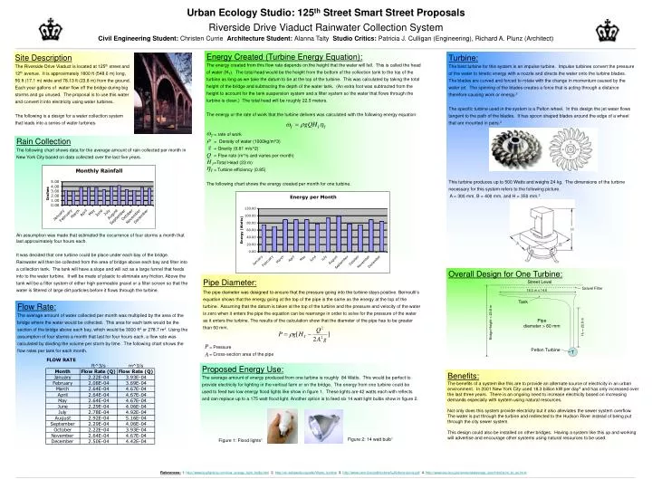
Urban Ecology Studio: 125th Street Smart Street Proposals Riverside Drive Viaduct Rainwater Collection System Civil Engineering Student: Christen Currie Architecture Student: Alanna Talty Studio Critics: Patricia J. Culligan (Engineering), Richard A. Plunz (Architect) Energy Created (Turbine Energy Equation): The energy created from this flow rate depends on the height that the water will fall. This is called the head of water (HT). The total head would be the height from the bottom of the collection tank to the top of the turbine as long as we take the datum to be at the top of the turbine. This was calculated by taking the total height of the bridge and subtracting the depth of the water tank. (An extra foot was subtracted from the height to account for the tank suspension system and a filter system so the water that flows through the turbine is clean.) The total head will be roughly 22.9 meters. The energy or the rate of work that the turbine delivers was calculated with the following energy equation: = rate of work = Density of water (1000kg/m^3) = Gravity (9.81 m/s^2) = Flow rate (m^/s and varies per month) =Total Head (23 m) =Turbine efficiency (0.85) The following chart shows the energy created per month for one turbine. Site Description The Riverside Drive Viaduct is located at 125th street and 12th avenue. It is approximately 1800 ft (548.6 m) long, 56 ft (17.1 m) wide and 78.13 ft (23.8 m) from the ground. Each year gallons of water flow off the bridge during big storms and go unused. The proposal is to use this water and convert it into electricity using water turbines. The following is a design for a water collection system that leads into a series of water turbines. Turbine: The best turbine for this system is an impulse turbine. Impulse turbines convert the pressure of the water to kinetic energy with a nozzle and directs the water onto the turbine blades. The blades are curved and forced to rotate with the change in momentum caused by the water jet. The spinning of the blades creates a force that is acting through a distance therefore causing work or energy.2 The specific turbine used in the system is a Pelton wheel. In this design the jet water flows tangent to the path of the blades. It has spoon shaped blades around the edge of a wheel that are mounted in pairs.2 This turbine produces up to 500 Watts and weighs 24 kg. The dimensions of the turbine necessary for this system refers to the following picture. A = 300 mm, B = 400 mm, and H = 350 mm.3 Rain Collection The following chart shows data for the average amount of rain collected per month in New York City based on data collected over the last five years. An assumption was made that estimated the occurrence of four storms a month that last approximately four hours each. It was decided that one turbine could be place under each bay of the bridge. Rainwater will then be collected from the area of bridge above each bay and filter into a collection tank. The tank will have a slope and will act as a large funnel that feeds into to the water turbine. It will be made of plastic to eliminate any friction. Above the tank will be a filter system of either high permeable gravel or a filter screen so that the water is filtered of large dirt particles before it flows through the turbine. Overall Design for One Turbine: Pipe Diameter: The pipe diameter was designed to ensure that the pressure going into the turbine stays positive. Bernoulli’s equation shows that the energy going at the top of the pipe is the same as the energy at the top of the turbine. Assuming that the datum is taken at the top of the turbine and the pressure and velocity of the water is zero when it enters the pipe the equation can be rearrange in order to solve for the pressure of the water as it enters the turbine. The results of the calculation show that the diameter of the pipe has to be greater than 60 mm. = Pressure = Cross-section area of the pipe Street Level Gravel Filter 18.3 m x 14.6 Tank Flow Rate: The average amount of water collected per month was multiplied by the area of the bridge where the water would be collected. This area for each tank would be the section of the bridge above each bay, which would be 3000 ft2 or 278.7 m2. Using the assumption of four storms a month that last for four hours each, a flow rate was calculated by dividing the volume per storm by time. The following chart shows the flow rates per tank for each month. Pipe diameter > 60 mm Bridge Height = 23.8 m HT = 22.9 m Pelton Turbine T Proposed Energy Use: The average amount of energy produced from one turbine is roughly 84 Watts. This would be perfect to provide electricity for lighting in the vertical farm or on the bridge. The energy from one turbine could be used to feed two low energy flood lights like show in figure 1. These lights are 42 watts each with reflects and can replace up to a 175 watt flood light. Another option is to feed six 14 watt light bulbs show in figure 2. Benefits: The benefits of a system like this are to provide an alternate source of electricity in an urban environment. In 2001 New York City used 18.3 billion kW per day4 and has only increased over the last three years. There is an ongoing need to increase electricity based on increasing demands especially with system using natural resources. Not only does this system provide electricity but it also alleviates the sewer system overflow. The water is put through the turbine and redirected to the Hudson River instead of being put through the city sewer system. This design could also be installed on other bridges. Having a system like this up and working will advertise and encourage other systems using natural resources to be used. Figure 2: 14 watt bulb1 Figure 1: Flood lights1 References: 1. http://www.buylighting.com/low_energy_light_bulbs.htm 2. http://en.wikipedia.org/wiki/Water_turbine3. http://www.irem.it/en/pdf/turbine%20dimensions.pdf4. http://www.eia.doe.gov/emeu/states/sep_sum/html/sum_pr_eu.html