Download
1 / 8
130 likes | 443 Views
Modelling of RF LDMOS Transistors Using BSIM3. B. Senapati, K. Ehwald, I. Shevchenko, V. Dykyy , and F. Fürnhammer. Outline. LDMOS device cross-section of LDMOS LDMOS model SPICE sub-circuit model for LDMOS using bsim3v3 JFET to model the pinch-off the drift-region

E N D
Modelling of RF LDMOS Transistors Using BSIM3 B. Senapati, K. Ehwald, I. Shevchenko, V. Dykyy,and F. Fürnhammer
Outline • LDMOS device cross-section of LDMOS • LDMOS modelSPICE sub-circuit model for LDMOS using bsim3v3 JFET to model the pinch-off the drift-region • Measurements and extractionsetup for RF and DC measurementsextraction tool • Results DC results and RF results • Conclusion
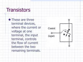
LDMOS Device Structure • LDMOS is fabricated into an advanced industrial 0.25µm BiCMOS process. • Source and substrate are common together to reduce the source resistance and inductance • Length of the drift region is 1mm • Gate length, width and finger number are 0.28mm, 5.6mm and 10, respectively K.-E. Ehwald et al., High Performance RF LDMOS Transistors with 5nm Gate Oxide in 0.25µm SiGe:C BiCMOS Technology, IEDM Tech. Dig, 2001
SPICE Sub-circuit Model of LDMOS • BSIM3v3 model for the intrinsic MOS • JFET model for the drift-region • AD, AS, PD and PS of BSIM3 are zero
Measurement Setup • DC-measurements (4142B) • using Kelvin probes • CV measurements (4284A) • RF measurements (PNA E8364A) 45 MHz - 50 GHz • Temperature range -40 °C - 200 °C • Software IC-CAP (version 2002)
Conclusion • LDMOS large signal model has been developed using BSIM3v3 • JFET used to model the pich-off of the drift region • Model includes dc including qusi-saturation, non- standerd capaciatce and high frequency • Model has been verified by comparing simulation with measurement • More accurate physical model required for modeling the drift region • On-going work is in the Self-heating and temperature modelling