Download
1 / 19
190 likes | 274 Views
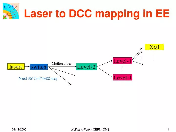
Laser to DCC mapping in EE. Xtal. Level-1. Mother fiber. Level-2. lasers. switch. Level-1. Need 36*2+4*4=88-way. 02/11/2005. 1. Wolfgang Funk - CERN CMS. 1. 5. 33a. 2. 6. 17. 18. 19. 33b. 3. 7. 20. 21. 22. 23. 29a. 4. 8. 24. 25. 26. 27. 28. 29b. 9. 13. 30.

E N D
Laser to DCC mapping in EE Xtal Level-1 Mother fiber Level-2 lasers switch Level-1 Need 36*2+4*4=88-way 02/11/2005 1 Wolfgang Funk - CERN CMS
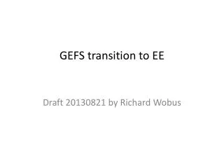
1 5 33a 2 6 17 18 19 33b 3 7 20 21 22 23 29a 4 8 24 25 26 27 28 29b 9 13 30 31 32 34 35 36 58a 10 14 37 38 39 40 41 42 43 11 15 44 45 46 47 48 49 50 12 16 51 52 53 54 55 56 57 58b 59 60 61 62 63 64 65 66 5 of 58c 1 of 29c 67 68 69 70 71 72 73 74 77 79 76 78 80 81 82 75 5 of 112a 1 of 119a 83 85 87 84 86 88 89 90 91 95 133 92 94 96 97 137 93 149a 138 99 101 103 134 100 102 104 98 139 106 108 110 135 107 109 111 105 X L-2 L-1 140 113 115 117 136 114 116 118 112b 145 120 122 124 141 121 123 112c 119b 146 130 128 142 126 125 119c 147 131 129 143 127 132a 148 144 Laser mapping for Dee2 and Dee4View from back of backplate For each laser switch position, 1 DCC to be read out for yellow, green, and pink regions and 2 DCCs for the combined blue and orange region !! -> firmware 4 (of 4) Level-2 fanouts (black, blue, brown, pink) 19 (of 20) Level-1 fanouts Max. 6 Level-1 per Level-2!! 12 (of 12) FEMs 220 Xtals per Level-1 in 4, 201 in 1, 210 in 2, 206 in 3, 220 in 5 (normally 200 of 240) 5 4 3 3 6 4 2 2 5 2 4 1 1 3 3 1 2 4 1
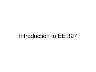
ECAL numbering scheme • CMS-note 2005/021 “CMS ECAL Barrel channel numbering”. • New numbering of SMs of EB (no change of the rest). • Numbering of trigger sectors in EE. • Numbering of data sectors in EE. • Scheme for both hardware and software. • Scheme has to be compliant with official CMS numbering scheme and the standard trigger system numbering. • ULR crate organization is organized as CMS trigger system demands. • In all sub-detectors the numbers are identical in each Φ-trigger slice. • After discussions with a lot of people new scheme has been accepted by the ECAL management. 02/11/2005 3 Wolfgang Funk - CERN CMS
HB+ numbering scheme near 02/11/2005 4 Wolfgang Funk - CERN CMS
HE+ numbering scheme near 02/11/2005 5 Wolfgang Funk - CERN CMS
HE- numbering scheme near 02/11/2005 6 Wolfgang Funk - CERN CMS
EB+- numbering scheme EB- EB+ far far SM6 SM5 SM5 SM6 near near SM7 SM4 SM4 SM7 SM8 SM3 SM3 SM8 SM9 SM2 SM2 SM9 SM10 SM1 SM1 SM10 +x +x SM11 SM18 SM18 SM11 SM17 SM12 SM12 SM17 SM13 SM16 SM16 SM13 SM14 SM15 SM15 SM14 Views from I.P. 02/11/2005 7 Wolfgang Funk - CERN CMS
EE+ trigger numbering near 02/11/2005 8 Wolfgang Funk - CERN CMS
EE- trigger numbering near 02/11/2005 9 Wolfgang Funk - CERN CMS
S1 S9 S2 S8 EE+ EE+N EE+F S3 93 S7 S4 S6 S5 EE+ data sector numbering near Viewed from the I.P. 02/11/2005 10 Wolfgang Funk - CERN CMS Viewed from the I.P.
S9 S1 S8 S2 EE- EE-F EE-N S7 S3 S6 S4 S5 93 EE- data sector numbering near Viewed from the I.P. 02/11/2005 11 Wolfgang Funk - CERN CMS Viewed from the I.P.
ULR crate matching 2 3 4 5 6 7 8 9 1 near 8/17 0/9 far Crate A1 Crate A far near Crate A2 EB EE SM5 SM6 7/16 S1 S9 SM7 SM4 1/10 87.7 (85.3) SM8 85.7 (83.3) SM3 Crate C2 S2 S8 87.7 (85.3)) 83.7 (81.3) SM9 SM2 Max. 61.4 SM10 Max. length of fibers up to 1. rack edge row left bottom corner SM1 85.2 (82.8) 81.7 (79.3) Crate B1 6/15 S7 2/11 S3 SM11 SM18 Crate C 82.2 (79.8) 80.2 (77.8)) 80.2 (77.8) SM17 SM12 SM13 SM16 S6 Crate B S4 SM15 SM14 Crate C1 S5 Crate B2 3/12 5/14 4/13 Max.total length of fibers 81.3+6.4=87.7 87.7+4.6=92.3 85.2+7.6=92.8 85.3+4.0=89.3 83.7+5.2=88.9 82.8+7.0=89.8 EE+ A 9-16-17 EE- A 0-7-8 EE- C 1-2-3 EE+ C 10-11-12 EE+ B 13-14-15 EE- B 4-5-6 SRP wall to UX EB+ A1 9-17 EB+ A2 16-17 EB+ C2 10-11 EB+ C1 11-12 EB+ B1 14-15 TST EB+ B2 13-14 Raw D EB- A1 0-8 EB- A2 7-8 EB- C2 1-2 EB- C1 2-3 EB- B1 5-6 EB- B2 4-5 0 9 1 10 2 11 3 12 4 E 17 8 16 7 15 6 14 5 13 rack1 rack2 rack3 rack4 rack5 rack6 rack7 02/11/2005 12 Wolfgang Funk - CERN CMS
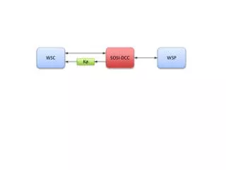
X L-2 L-1 Laser distribution system general • Laser station is connected via switch to mother fibers. • Switch has to be at least (2x36 + 4x4) = 88-way. Maybe 92-way? • Each mother fiber (coming from the laser switch in laser • barrack) has one Level-2 fanout. • Each Level-2 fanout has 7 fibers going out towards one • Level-1 fanout, where normally 5 are installed. • Each Level-1 fanout has 240 fibers going out towards the Xtals, • where at least 200 working fibers have to be available for Xtals. • Each Level-2 fanout has one fiber to a PN diode in a FEM. • Each Level-1 fanout has one fiber to a PN diode in a FEM. • Each FEM has 2 PN diode either for Level-1 or Level-2 (not • mixed). • Each FEM has 2 read-out cables to (Double) MEM-box. 20/09/2005 2 Wolfgang Funk - CERN CMS
X L-2 L-1 Laser distribution system EE specific • 6 mother fibers per Dee are installed in pt5. Need spares! • 4 Level-2 fanouts per Dee are foreseen. • 20 Level-1 fanouts per Dee are foreseen. • If possible, each fiber connected to one Level-1 should get • similar radiation dose. • 12 FEMs (24 PN diodes) per Dee are foreseen. • Power cables for 12 FEMs are installed in pt5. • 24 read-out cables per Dee from FEMs to Double MEM (has • 24 ADCs) are installed in pt5. • Double MEM reads 2 Quadrant (≡ 2 SMs) 20/09/2005 3 Wolfgang Funk - CERN CMS
X L-2 L-1 Data sector/DCC architecture EE specific • Per Dee there are 4 ½ data sectors. • Each data sector has one specific DCC in the ULR. • Laser trigger information is sent to DCCs, to determine which • DCC is read out. • All Xtals in this data sector are then read out. • To read out several data sectors, a special bit pattern is used, • special firmware would need to be developed. 20/09/2005 4 Wolfgang Funk - CERN CMS
1 5 33a 2 6 17 18 19 33b 3 7 20 21 22 23 29a 4 8 24 25 26 27 28 29b 9 13 30 31 32 34 35 36 58a 10 14 37 38 39 40 41 42 43 11 15 44 45 46 47 48 49 50 12 16 51 52 53 54 55 56 57 58b 59 60 61 62 63 64 65 66 5 of 58c 1 of 29c 67 68 69 70 71 72 73 74 77 79 76 78 80 81 82 75 5 of 112a 1 of 119a 83 85 87 84 86 88 89 90 91 95 133 92 94 96 97 137 93 149a 138 99 101 103 134 100 102 104 98 139 106 108 110 135 107 109 111 105 X L-2 L-1 140 113 115 117 136 114 116 118 112b 145 120 122 124 141 121 123 112c 119b 146 130 128 142 126 125 119c 147 131 129 143 127 132a 148 144 Former EE laser mapping For each laser switch position, 2-3 DCCs to be read out!! 4 Level-2 fanouts (black, blue, brown, pink) 20 Level-1 fanouts Max. 5 Level-1 per Level-2 12 FEMs Max. 215 Xtals per Level-1 (5, 5) 4 4 5 5 3 3 5 5 2 2 1 1 1 2 3 3 2 4 4 1 20/09/2005 5 Wolfgang Funk - CERN CMS
1 5 33a 2 6 17 18 19 33b 3 7 20 21 22 23 29a 4 8 24 25 26 27 28 29b 9 13 30 31 32 34 35 36 58a 10 14 37 38 39 40 41 42 43 11 15 44 45 46 47 48 49 50 12 16 51 52 53 54 55 56 57 58b 59 60 61 62 63 64 65 66 5 of 58c 1 of 29c 67 68 69 70 71 72 73 74 77 79 76 78 80 81 82 75 5 of 112a 1 of 119a 83 85 87 84 86 88 89 90 91 95 133 92 94 96 97 137 93 149a 138 99 101 103 134 100 102 104 98 139 106 108 110 135 107 109 111 105 X L-2 L-1 140 113 115 117 136 114 116 118 112b 145 120 122 124 141 121 123 112c 119b 146 130 128 142 126 125 119c 147 131 129 143 127 132a 148 144 Possible EE laser mapping (2) For each laser switch position, only 1 DCCs to be read out!! 5 Level-2 fanouts (black, blue, brown, pink,green)!! 23 Level-1 fanouts!! Max. 5 Level-1 per Level-2 15 FEMs (12 foreseen)!! Max. 200 Xtals per Level-1 1 2 2 1 3 4 1 4 3 3 2 2 5 4 4 5 5 1 5 2 1 3 3 20/09/2005 7 Wolfgang Funk - CERN CMS
1 5 33a 2 6 17 18 19 33b 3 7 20 21 22 23 29a 4 8 24 25 26 27 28 29b 9 13 30 31 32 34 35 36 58a 10 14 37 38 39 40 41 42 43 11 15 44 45 46 47 48 49 50 12 16 51 52 53 54 55 56 57 58b 59 60 61 62 63 64 65 66 5 of 58c 1 of 29c 67 68 69 70 71 72 73 74 77 79 76 78 80 81 82 75 5 of 112a 1 of 119a 83 85 87 84 86 88 89 90 91 95 133 92 94 96 97 137 93 149a 138 99 101 103 134 100 102 104 98 139 106 108 110 135 107 109 111 105 X L-2 L-1 140 113 115 117 136 114 116 118 112b 145 120 122 124 141 121 123 112c 119b 146 130 128 142 126 125 119c 147 131 129 143 127 132a 148 144 Possible EE laser mapping (3) For each laser switch position, only 1 DCCs to be read out!! 5 Level-2 fanouts (black, blue, brown, pink,green) 18 Level-1 fanouts Max. 5 Level-1 per Level-2 12 FEMs!! 220 Xtals per Level-1 in 4, 201 in 1, 220 in 1, 210 in 4, 206 in 1, 220 in 4, 210 in 2 3 4 4 3 3 2 2 4 2 1 2 1 1 3 1 2 4 1 20/09/2005 8 Wolfgang Funk - CERN CMS
X L-2 L-1 What is the best? For an external viewer (3)Independent firing of all data sectors! One more Level-2, two less Level-1. Same number of FEMS as foreseen. Need switch with 72 (EB) + 20 (EE) = 92! 20/09/2005 9 Wolfgang Funk - CERN CMS