Download
1 / 8
80 likes | 225 Views
Service. type. #cables. L avg. L tot. Costs est [ksfr]. LV. 50mm 2 , (1). 320. 18. 5760. 26 (US?). EE fibres. yellow ribbons. 420+33. 26. 11788. US. HV. (SCEM 04.61.11.145.5) 25 (13+12) together in bundle. (1300) 52 bundles. 26+100. 6552. 75. Control (LVR+sense). 48.

E N D
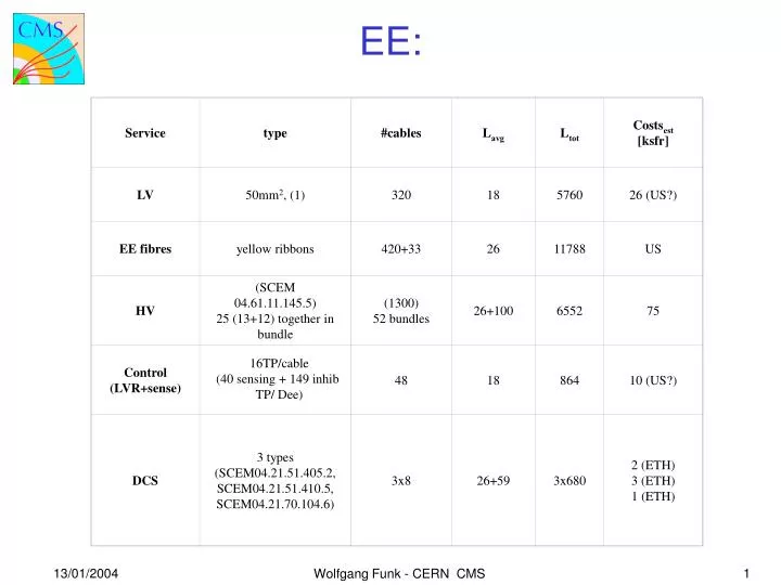
Service type #cables Lavg Ltot Costsest [ksfr] LV 50mm2, (1) 320 18 5760 26 (US?) EE fibres yellow ribbons 420+33 26 11788 US HV (SCEM 04.61.11.145.5) 25 (13+12) together in bundle (1300) 52 bundles 26+100 6552 75 Control (LVR+sense) 48 18 864 10 (US?) DCS 3 types (SCEM04.21.51.405.2, SCEM04.21.51.410.5, SCEM04.21.70.104.6) 3x8 26+59 3x680 2 (ETH) 3 (ETH) 1 (ETH) EE: 16TP/cable (40 sensing + 149 inhib TP/ Dee) 13/01/2004 1 Wolfgang Funk - CERN CMS
MEM coax 96 2 (Dee-MEM) 192 Saclay MEM TP bus 16 2 (Dee-MEM) 32 Saclay MEM ring 24 2 (Dee-MEM) 48 Saclay MEM Hybrid 8 18 (MEM-PSU) 144 Saclay MEM Ving+sense 4 100 PSU-US5) 400 Saclay MEM fibres yellow ribbons 4+4 25 (MEM-outs) 200 Saclay MEM laser fibres 4 26+120 584 Saclay SCEM04.61.11.105.3 SCEM04.21.22.410.6 Radiospares3118255 LAPP Muller 54744/B Nexans (ATLAS prod.) defined 13/01/2004 2 Wolfgang Funk - CERN CMS
Service type #cables Lavg Ltot Costsest [ksfr] LV 16mm2 10mm2 320 320 20 12800 13 Fibres yellow ribbons 152 27 4104 US HV SCEM 04.31.52.100.5 76 26+120 11096 71 Control (LVR,sense,DCS) SCEM 04.70.03.000.7? 84 20 1680 20 ? ES: Total number of cables: EE: 1057 ES: 952 Total length of cables: EE: 28604m ES: 29680m missing: green Ericson fibre cables: 72 (EE) and 19? (ES) 13/01/2004 3 Wolfgang Funk - CERN CMS
problems to be solved before ordering (1) LV EE :(50mm**2 copper bus bares, sense wires, control-wires for LVRs) : several tests have to be made before we really know if our present baseline is valid. Critical issue is the PSU prototype from CAEN delivered beginning of '04 if we are lucky. Present Baseline: 2 cables (aller, retour) and one 100A PSU per mostly 100crystals, grounding made to cooling bars and backplate, sensing made at distribution box close to each 100crystals, inhibit on/off lines for all LVRs not dealing with control, one common inhibit line per LVR card. Requested tests: analogue/digital power together, sensing, control system architecture verification, AC/DC boxes, PSU, connecting scheme at patch-panel, grounding, LVR radiation tests, inhibit level degradation with radiation? Are the unshielded cables sufficient? Sense and control cables have not yet been selected. LV ES : (16mm**2 and 10mm**2 bus bares, control-wires for LVRs); very recently the baseline has been changed from 6X 16mm**2 to 4X16mm***2 and 4X10mm**2 per feedtrough. Like this we can avoid huge ground loops outside of ES. Electronics to do tests is not yet ready. If we are lucky first tests can be made beginning '04. Present Baseline: 4 cables (aller, retour) 16mm**2 for analogue and 4 cables 10mm**2 for digital and control per feedthrough (1 feedthrough feeds 2 rings normally). Most of control rings are getting power through 2 feedtroughs. One 100A PSU subdivided into 4X 25A supplies per control ring, the 4 subsupplies deliver power for analogue-feedthrough1, analogue-feedthrough2, digital/control-feedthrough1, digital/control-feedthrough2. Grounding made via mechanics inside ES, no sensing, inhibit on/off lines for all analogue and digital regulators together with one line per motherboard leads to 12 Inhibits, Inhibit on/off lines for all GOH regulators with one line per motherboard leads to another 12 Inhibits. CAEN A3100 delivers 24 Inhibits!) Requested tests: analogue/digital power together, sensing, control system architecture verification, AC/DC boxes, PSU, grounding, removal of parasitic powering of chips via clock etc. coming from CCU, LVR radiation tests, inhibit level degradation with radiation? Decision about overcurrent bit, decision about sensing. Taking the return current for the analogue through the structure back out. Are the unshielded cables sufficient? Control cables have not yet been selected (see DCS ES chapter). 13/01/2004 4 Wolfgang Funk - CERN CMS
problems to be solved before ordering (2) Fibers EE: (standard yellow ribbons run in the ducts). The whole system architecture has never been really defined, very recently we started this activity. The problem is that the standard tracker architecture is not applicable, therefore new technical solutions have to be found, developed and verified. The aim is clearly to use as much as possible from the original tracker system. The baseline is a MFS housing (if possible the 4-way) at the patch-panel, where the yellow ribbons start through the ducts. Problems and questions: Can we find the space for 43 boxes (boxes used to go from 12pigtails into 1 yellow ribbon) per Dee inside? (Tony and John are trying hard!). If yes, the length of yellow ribbon to MFS connector is most probably inside the tracker contract, but we need several different lengths! If not ,the so-called distributed patch panel connector has to be placed close to the EE patch panel, Therefore the length of fibers+furcation element+yellow ribbon is shorter than in tracker contract. The yellow ribbon has to cover fully the fibers up to connector entrance for protection reasons maybe not inside, but certainly at the other side at the outside of the EE patch panel. Different strain release schemes are under discussion. We found a possible mechanical problem with the 4 way-MFS housing and the MFS connector with our preferred strain release option. Is Diamond willing to produce what we need? Fibers EE: (standard yellow ribbons run in the ducts). The whole system architecture has never been really defined, very recently we started this activity together with EE, see above). The problem is that the standard tracker architecture is not applicable, therefore new technical solutions have to be found, developed and verified. The aim is clearly to use as much as possible from the original tracker system. The baseline is a single way MFS housing (not in the tracker contract and not promoted by Diamond, but in their catalogue?) placed at the fingers where ES is fixed on EE. The furcation element sits in the feedthrough. There is no distributed patch panel connector, since there is no space. Instead we splice the fibers inside ES before the furcation element. Problems and questions: The length of the furcation element+yellow ribbon up the MFS connector is shorter than in tracker contract. The yellow ribbon has to cover fully the fibers up to the connector entrance for protection reasons on both sides of the MFS housing. Different strain release schemes are under discussion. Is the single MFS housing adequate? 13/01/2004 5 Wolfgang Funk - CERN CMS
problems to be solved before ordering (3) HV EE: (single coax for both voltages in bunches). Baseline: for 12 SCs we will have one bundle of 25 (12+13) coax (1 spare) with one connector for 25 coax on each side. For both endcaps we will have 52 cable bunches. Presently tests with the baseline connector and cables are performed at RAL. Tests should be finished this year. We believe that we will handle those 25 (12+13) coax as 1 cable with one connector at each side. Companies will gave quotations for individual coaxes and bunch coax cable. HV EE:(Multi Conductor Cable). Baseline: 76 cables for both endcaps. Tests have been successfully finished. DCS EE: (Multi Twisted pair cable) As far as I know nobody has seriously worked on DCS aspects in EE. Therefore before better knowing I assume the same number of types and sensors as in EB (1 Quadrant=1 SM). The baseline cables of EB would as well fulfill the radiation requirements of EE. Baseline: 3 different multi twisted pair cable for the 3 different DCS systems. PTM (Precision Temperature Monitoring STP 21x2) HM (Humidity Monitoring STP 4x2), TSS (Temperature Safety System, STP 9x2) Problems and questions: Is the number of sensors as I have extrapolated from EB correct? Is the baseline humidity sensor radiation resistant up to EE radiation dose? DCS ES: (Multi Twisted pair cable together with control-wires for LVRs).Dave Barney has prepared a paper on ES DCS. The 100KOhm thermistors used in EB and EE have to be tested for radiation resistance. A 2-wire readout of those should provide the precision of the temperature which is required. Is the baseline humidity sensor radiation resistant up to ES radiation dose? Is the present read-out scheme with ELMBs or the Tracker read-out scheme better (this changes length of cables and therefore might force us to use more wires)? Since the final number of DCS wires is not known and the the number of control-wires for LVRs is not yet fixed (see above) no selection of the cable can yet be done. 13/01/2004 6 Wolfgang Funk - CERN CMS
problems to be solved before ordering (4) MEM EE: (several types of cables between the Dee and the MEM box and between the MEM box and outside) Between the Dee and the MEM box: MEM coax, MEM TP bus, MEM ring. Between the MEM box and outside dispatch box: Hybrid (MEM LV 5V, MEM 2.5V, MEM Ving, MEM sense for all three) , Between the MEM box and the outside: OF yellow ribbon Between the Dee and the outside: MEM laser sheath (6 fibers). Between the dispatch box and the outside: MEM Ving and MEM sense for Ving in one cable Cables are close to be finally defined. A meeting will take place in Saclay in January. The yellow ribbons are standard ones, the laser fiber sheath which was initially proposed is too thick, we look for other solutions. The laser fibers will be spliced or glued at the intermediate patch panel under the balconies. The hybrid cable will end at the dispatch box (close to the PSUs) in the balconies. For the LV a 5A Caen PSU with 12channels could be used, since the output voltage can go up to 8V. One channel would deliver 5V another 8V. The requested current per MEM box is 2 X2A per single MEM box. Per endcap we would need 8 (2X4) PSU-channels. This is all contained in one module. The MEM sense wires would end as well at the PSU.Ving and its sense cables will leave dispatch box via laser barrack. EE and ES Dummies: We are progressing quite well, there is good hope to have all in time. A part of the EE and ES Dummies will be the EE and ES patch panels (see below). The ducts between EE and ES patch panels are well advanced. EE patch panel: It is needed to do the cabling. Apart from very rough ideas, nothing is known and fixed. This concerns layout and connector types. The layout can only seriously been worked on if the so-called 'mechatronics' is finalised. Tony and John are working on it. Schedule:? ES patch panel:It is needed to do the cabling. Piet has quite good ideas how it should look like. If the choices of architecture of the different services and the choices of the cables are made, I am confident that Piet will finalize design quite rapidly. 13/01/2004 7 Wolfgang Funk - CERN CMS
problems to be solved before ordering (5) MEM box Dummy:It is needed to do the cabling. Meetings will take place at Saclay in January to understand where we could place the connectors etc. Schedule: delivery Sept.04. Cable lengths: calculation is underway. Purchasing and 'Greek connection‘: Our geek collaborators are willing to spend money on EE and ES cables (as well connector mounting). The condition on this it that the money has to be spend in Greece. After a long search we found a french based company which has a subsidiary in Greece and is capable to produce several of our cables. Prices are correct. In the moment we enquire how our greek colleagues could purchase the cables, via the 'magasin' of CERN, cables to Greece and then to CERN, etc. How long this takes and if the whole effort is successful, I can't predict. Since for several cable types we do not yet know who could pay if not the Greeks as EE HV, all of ES, I am unable to present any delivery schedule. 13/01/2004 8 Wolfgang Funk - CERN CMS