Download
1 / 20
200 likes | 573 Views
Design of Power Capacitor For Power Factor Improvement In A Power Distribution System. High Voltage Laboratory. Power Capacitor. Team and Responsibilities. Team Leader Parson L.B – Coil and discharge resistor Members Page J.C – Bushing and withstand/impulse test

E N D
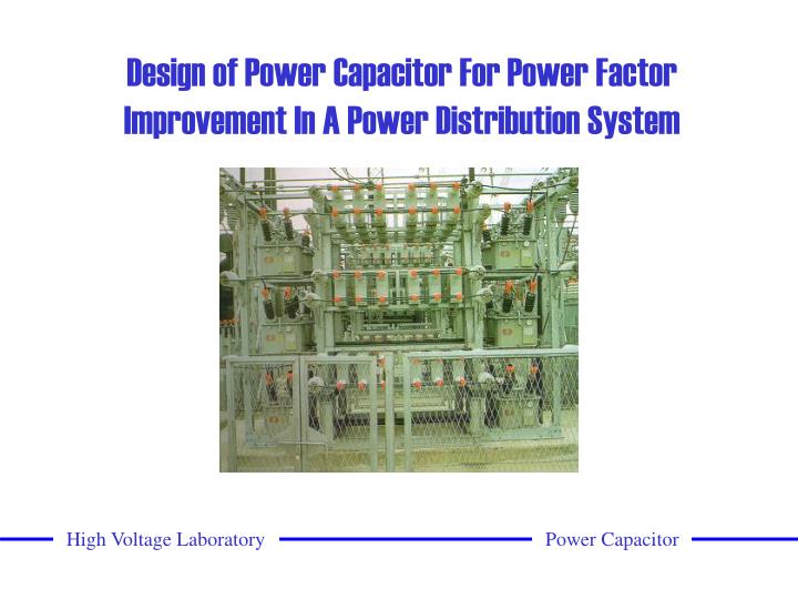
Design of Power Capacitor For Power Factor Improvement In A Power Distribution System High Voltage Laboratory Power Capacitor
Team and Responsibilities • Team Leader • Parson L.B – Coil and discharge resistor • Members • Page J.C – Bushing and withstand/impulse test • Watson K.M – Coil and discharge resistor • Wong C.S – Bushing and withstand /impulse test • Advisor • Dr. Stanislaw Grzybowski High Voltage Laboratory Power Capacitor
Abstract Design power capacitors to maximize a distribution system’s overall performance High Voltage Laboratory Power Capacitor
Problem 1. Voltage drop 2. Energy losses 3. Decreased system capacity Low power factor High Voltage Laboratory Power Capacitor
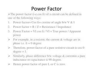
Why correct power factor ? Efficiency of Power Distribution System $$$ Deregulation of Power Distribution System Energy Losses Power Quality High Voltage Laboratory Power Capacitor
Design Requirements 1. The voltage rating across the capacitor will be 8.66kV 2. Provide a total reactive power of 2 MVAr 3. Reduce voltage drop by 5% 4. Reduce energy loss by 30% 5. Achieve an optimum power factor of at least 90% 6. Reduce current in power lines by 15% 7. Increase system capacity by 20% 8. Discharge to under 50V in less than 5 minutes 9. Low dielectric losses (tan ) (< 0.1W per kVAr) High Voltage Laboratory Power Capacitor
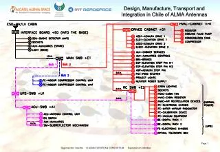
Design Implementation High Voltage Laboratory Power Capacitor
Design Implementation High Voltage Laboratory Power Capacitor
Design Implementation High Voltage Laboratory Power Capacitor
Capacitor Construction Individual coil Cutaway view of capacitor High Voltage Laboratory Power Capacitor
Capacitor Components Aluminum Foil 1. Lightweight 2. Good conductor 3. Less expensive than other available conductors Polypropylene dielectric 1. Yields high dielectric constant 2. High voltage stress rating 3. Low dielectric losses Use of oil to impregnate dielectric 1. Better cooling properties 2. Increases maximum electrical stress High Voltage Laboratory Power Capacitor
Design Process 1. Total reactive power of 2MVAR in 15kV substation 2. Each capacitor will supply 50kVAR 3. The capacitance for each capacitor is 1.901F 4. Each capacitor will have 6 coils in series and 2 in parallel High Voltage Laboratory Power Capacitor
Design Process 5. The capacitance for each coil is 5.73F 6. The thickness of dielectric 0.02mm 7. The area of foil and dielectric is 2.942m2 8. The length of foil and dielectric is 23.165m with 5in. (12.7cm) polypropylene 9. The discharge resistor will be 15M High Voltage Laboratory Power Capacitor
Simulation Results Reduce voltage drop by 5% Reduce energy loss by 30% Achieve an optimum power factor of at least 90% Reduce current in power lines by 15% Increase system capacity by 20% Discharge Capacitor in less than 5 minutes Load voltage increased (13.8kV to 14.44kV): 4.6% improvement Energy loss decreased (76.7kW to 44.7kW): 41.7% reduction Power factor increased (0.7 to 0.956) Current decreased (141.77A to 108.49A): 23.5% reduction System capacity increased: 40.4% improvement Discharged from 15kV to <50V: 3 minutes High Voltage Laboratory Power Capacitor
Tests • 1. Test capacitance • 2. Measure dielectric losses (tan ) • Transformer Arm Ratio Bridge • 3. Withstand Voltage Test • Energize with DC between terminals • Vsource = 4 x Vrated for 10 seconds (IEEE Standard 18-1992) • Energize with AC between terminals and ground • Vsource = 40kV for 10 seconds (IEEE Standard 18-1992) • 4. Lightning Impulse Test (1.2/50s) (IEEE Standard 18-1992) • 5. Discharge Test High Voltage Laboratory Power Capacitor
Tests Lightning Impulse Test (wet condition) High Voltage Laboratory Power Capacitor
Tests Results • 1. Test capacitance (1.989F) • 2. Measure dielectric losses (tan < 0.07w per kVAr or 3.5w) • Transformer Arm Ratio Bridge • 3. Withstand Voltage Test • Energize with DC between terminals • Successfully maintain voltage for 10 seconds • Energize with AC between terminals and ground • Successfully maintain voltage for 10 seconds • 4. Lightning Impulse Test • No dielectric breakdown observed • 5. Discharge Test (Vcap < 50V in <5min.) High Voltage Laboratory Power Capacitor
Future Works Research dielectrics to provide better insulation properties New lighter materials to reduce overall weight Design a control system to automatically regulate the power factor High Voltage Laboratory Power Capacitor
DEMO DEMO High Voltage Laboratory Power Capacitor
References High Voltage Laboratory Power Capacitor