Download
1 / 37
370 likes | 1.07k Views
Flammability Characteristics of JP-8 Fuel Vapors Existing Within a Typical Aircraft Fuel Tank. Steven M. Summer Department of Mechanical & Aerospace Engg. Masters Thesis Defense December 21, 2000 Faculty Advisor: Prof. C. E. Polymeropoulos. Overview of Problem.

E N D
Flammability Characteristics of JP-8 Fuel Vapors Existing Within a Typical Aircraft Fuel Tank Steven M. Summer Department of Mechanical & Aerospace Engg. Masters Thesis Defense December 21, 2000 Faculty Advisor: Prof. C. E. Polymeropoulos
Overview of Problem • Threat of ignition of fuel vapors within aircraft fuel tanks • Has long been noted, but until recently, not much data • Several protection systems have been researched and proposed, but none implemented in commercial aircraft
Overview of Problem • July 1996, TWA 800 crashes over East Moriches, NY • NTSB cites an in-flight fuel tank explosion as cause • Numerous research projects undertaken by CIT, UNR, ASU, SWRI and others • Overall goal: generate enough data on aviation fuel vapor generation/flammability to be able to develop a means of protecting against ignition
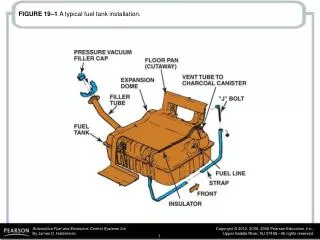
Overview of Problem: Aircraft Fuel Tanks • Fuel is typically is stored in two wing tanks • Larger aircraft also use a Center Wing Tank (CWT) located within fuselage Definition: Fuel Mass Loading - (Mass of Liquid Fuel)/(Total Internal Tank Volume)
Aviation Rulemaking Advisory Committee Fuel Tank Harmonization Working Group Overview of Problem: Aircraft Fuel Tanks • In some cases, located directly underneath CWT is the Environmental Conditioning System (ECS) • Hot bleed air from the ECS heats CWT fuel, resulting in an increase of the FAR • ARAC’s FTHWG determined that these tanks are at risk 30% of the total flight time compared to 5% for CWT’s without ECS
Overview of Problem:Aviation Fuel • Specifications for commercial grade fuel (Jet A/Jet A-1 & Jet B) set forth by ASTM D1655 • Sets min/max values for things such as flash point, boiling point, freezing point, etc. • Very vague criteria for actual composition of the fuel
Overview of Problem:Aviation Fuel “These fuels shall consist of refined hydrocarbons derived from conventional sources including crude oil, natural gas liquids, heavy oil, and tar sands” -ASTM D1655
Reduced Summary of Problem • CWTs with adjacent heat sources (ECS) • Increases rate of fuel vapor generation • Typically small amount of fuel in CWT • Reduced impact on flammability because of increased evaporation of light ends • Lack of a definitive composition of aviation fuels • Leads to fuels consisting of hundreds of hydrocarbons, with varying properties Result: Fuel Tank Flammability Potential is Increased Throughout Flight Profile
Objectives • Heated Fuel Vapor Testing • Determine the effects of • fuel mass loading, • liquid fuel evaporative surface area and • residual fuel on tank walls and on ullage vapor generation within an aircraft fuel tank environment Definition: Ullage - the unused internal portion of the fuel tank
Objectives • Heated Fuel Vapor Testing With Tank Wall Cooling: • Determine the effects of cold tank wall temperatures on ullage vapor generation within an aircraft fuel tank environment
Objectives • Lower Oxygen Limit of Flammability Testing: • Determine the lowest oxygen level within the tank that will support ignition of the ullage fuel vapors (i.e. LOLF)
Heated Fuel VaporTesting: Objectives • Determine the effects of • fuel mass loading, • liquid fuel evaporative surface area and • residual fuel on tank walls and on ullage vapor generation within an aircraft fuel tank environment
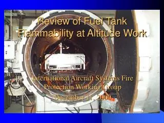
Heated Fuel VaporTesting: Apparatus • 88.21 ft3 vented, aluminum fuel tank • 14 K-type thermocouples • 1 Fuel • 5 Surface (3 wall, 2 ceiling) • 5 Ullage • 2 hydrocarbon sample ports • 150,000-Btu kerosene air heater • Several sized fuel pans • 1 x 1 , 2 x 2 and one covering tank bottom
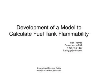
Analyzer Port 2 Door T/C 5 T/C 2 T/C 4 T/C 1 Analyzer Port 1 T/C 0 T/C 3 Heat Inlet Heat Outlet
Heated Fuel VaporTesting: Procedures • Fuel measured and poured into fuel pan • Fuel pan placed into tank • Tank door sealed • Kerosene air heater turned on • Fuel heated to 10° above flash point (125 °F) • Hydrocarbon concentration monitored until equilibrium is reached
Tank Wall Cooling:Objectives • Determine the effects of cold tank wall temperatures on ullage vapor generation within an aircraft fuel tank environment
Tank Wall Cooling:Apparatus • Same tank as Heated Fuel Vapor Testing with some modifications: • 3-in. shell surrounded the two side and rear walls for CO2 cooling • Kerosene air heater replaced with a thermostatically controlled hot plate
Tank Wall Cooling:Procedures • Fuel measured (1.5 gallons) and poured into fuel pan • Fuel pan placed into tank & tank door sealed • Hot plate turned on • Fuel heated to 10° above flash point (125 °F) and maintained for 2 hours • Walls were cooled to desired temperatures and maintained until significant decrease in HC concentration was observed
LOLF Testing:Objectives • Determine the lowest oxygen level within the tank that would support ignition (i.e. the lower oxygen limit of flammability)
LOLF Testing: Apparatus • 9 ft3 vented, aluminum fuel tank placed inside of 10 m3 pressure vessel equipped with: • 12 K-type thermocouples • 1 Fuel • 7 Surface (3 floor, 1 on each side wall) • 4 Ullage • 9.5" x 9.5" fuel pan located in center of tank • Thermostatically controlled hot plate • 6" diameter mixing fan • 2 hydrocarbon sample ports • 1 oxygen sample port • Spring loaded blow-out plate • Two tungsten electrodes powered by a 20,000 VAc, 20 mA transformer
LOLF Testing: Apparatus
LOLF Testing: Procedures • Fuel measured (3/8-gallon) & placed in pan • Fuel pan placed in center of tank • Nitrogen injected until desired O2 concentration reached • Hot plates turned on • Fuel heated to and maintained at ~150°F until HC concentration leveled off at ~25000 ppm C3H8 • Spark initiated for 1, 2 & 3 second durations
Conclusions • Heated Fuel Testing • At mass loading of 0.08 – 0.15 kg/m3 significant reduction in HC concentration • Evaporative surface area has no effect on HC concentration • As evaporative surface area decreases, longer time necessary to obtain maximum HC concentration • Residual fuel has no effects
Conclusions • Tank Wall Cooling Testing • As tank wall temperatures decrease, the rate of decrease in HC concentration increases • LOLF Testing • Methane LFL of 5.3 – 5.35% determined • LOLF determined to be 12% O2
Recommendations • Tank wall & ullage temperatures need to be treated carefully • Further LOLF experiments should include dynamic pressure instrumentation • LOLF at altitude