Download
1 / 28
280 likes | 500 Views
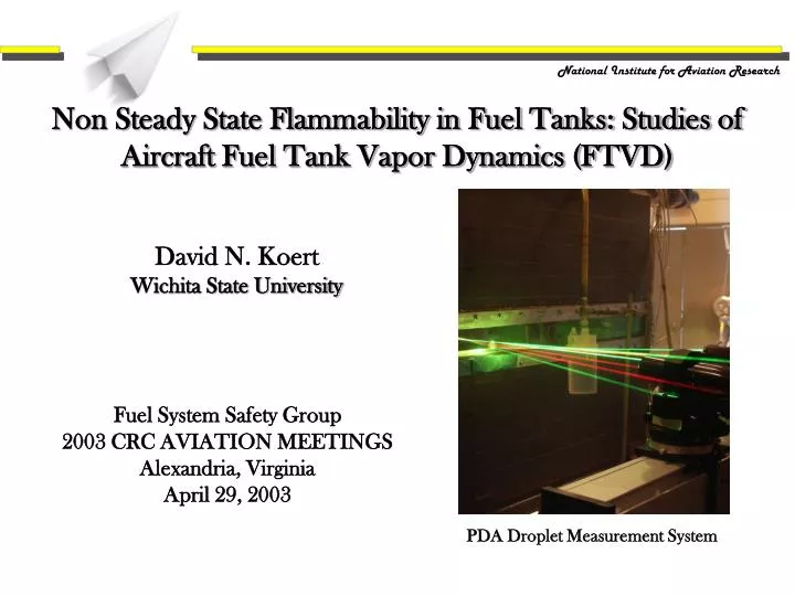
Non Steady State Flammability in Fuel Tanks: Studies of Aircraft Fuel Tank Vapor Dynamics (FTVD). National Institute for Aviation Research. David N. Koert Wichita State University. Fuel System Safety Group 2003 CRC AVIATION MEETINGS Alexandria, Virginia April 29, 2003.

E N D
Non Steady State Flammability in Fuel Tanks: Studies of Aircraft Fuel Tank Vapor Dynamics (FTVD) National Institute for Aviation Research David N. Koert Wichita State University Fuel System Safety Group 2003 CRC AVIATION MEETINGS Alexandria, Virginia April 29, 2003 PDA Droplet Measurement System
Motivation • Seek answers to key questions regarding: • Conditions at which fuel fog is formed • Flammability of the resulting air/fuel‑vapor/fuel‑aerosol mixture • Provide insight to supplement development of onboard inerting systems • Fuel fog formation occurs at conditions relevant to wing tanks • Results may be pertinent in development of control systems for onboard inerting systems
Project Overview • Conduct experimental studies in Fuel Tank Test Cell (FTTC) • Supersaturated fuel vapor will condense to form fuel fog • Study fog formation by thermal/mass diffusion • Fuel (liquid) in bottom of tank is “hot” relative to the ullage above • “Pre-fight scenario” • Primary mechanism of fog formation • Study fog formation by adiabatic decompression • Fuel (vapor) in ullage is cooled during decompression • “Takeoff scenario” • Secondary mechanism of fog formation • Identify conditions that promote droplet formation in fuel tanks • Understand vapor dynamics to minimize explosive conditions
Influence of Suspended Droplets on the Lower Flammability Limit • Fuel droplets in fuel-vapor air mixture may reduce the lower flammability limit • Dependent on fuel air ratio • Also dependent on droplet number density and droplet size distribution (Burgoyne and Cohen, 1954; Ott, 1970) • Transition from vapor flammability (<10μ) to droplet flammability (>40 μ) • Burgoyne and Cohen • Tetralin aerosols formed by homogenous gas-phase nucleation in a 5.4 cm tube • LFL of droplet-vapor-air ½ that of vapor-air Variation with Droplet Size of (a) the Lower Limit of Flammability, (b) Average Limit Flame Temperature [Burgoyne and Cohen, 1954]
Key Questions • How is condensed fuel replenished by additional fuel vapor? • Does convective mixing affect total mass of fuel vapor? • How does the Lower Flammability Limit (LFL) of evaporated fuel vapor and condensate compare to the published LFL for Jet A? • What is the impact of this on Fleet Flammability exposure?
Key Aspects of Experimental Observations • Fuel vapor transport is rate limited by convective fluid transport rather than molecular diffusion • Diffusional phenomena induced by temperature differences are primary “cause” of gas-phase condensation • Adiabatic decompression is only a secondary source of condensate • Surface condensation competes with gas-phase condensation • No simple relationship of fuel -vapor/-condensate mass to the equilibrium-based LFL estimate exists • These observations begin to answer Key Questions and lead to a Phenomenological Model of Fuel Tank Vapor Dynamics
Main Points of Remaining Discussion • Design and measurement capabilities of the WSU FTTC experimental facility • Experimental and modeling results related to fuel vapor transport and gas-phase condensation • Experimental results related to competition between surface condensation and gas-phase condensation • Modeling results indicating the role of an “evaporation layer” • Phenomenological Model of Fuel Tank Vapor Dynamics • Discussion of additional needs for experimental work to answer questions about the non-equilibrium LFL and fleet flammability exposure
Test Facility Design • FTTC • 2 x 1 x 1 m (≈ 640 gal.) • Design 1000 ft/min climb • Optical access • Eductor pump system • Water-Jet w/control valve • Constant vacuum, Psat@Tw • Surface heating-cooling • 18 kW heater/chillers • Surface-mount heat exchangers • Computer control system • Tank p-T control • Data logging Heat Exchanger Eductor Pump Heater/Chiller Window Fuel Tank Test Cell (FTTC) Indicating Related Systems
TC1-TC4 Measuring Ullage Gas Temperature TC6 13cm Fuel Tank TC1 TC2 TC3 TC4 26cm 39cm PDA Measurement Point (20 cm inside) 52cm TC5 TC7 Video Camera PDA 13cm TC8 35cm Line Laser Laser Sheet Windows Measure Systems on FTTC Experimental Facility Thermocouple Locations in FTTC FTTC Measurement Systems
Results from Experiment 1 • Tank bottom heated, top cooled • Conditions: • Argon atmosphere • 10 gal Jet A (1% mass loading) • Tank top 50 °F • Fuel 90 – 110 °F • Cloud 1st observed at 90 °F
Results from Experiment 1 • Stills and video taken • Backlit with incandescent light • Video quality is unconvincing • Photo shows cloud but not the vigorous flow field
Results from Baseline01 (Experiment 7) • View the video named “clip05”
Results from Baseline05 (Experiment 15) • View the video named “clip02”
Comments on the Videos from Experiments 7 &15 • The presence and motion of droplets illuminated by the laser sheet indicates: • Cloud formation due to condensation of sub-cooled fuel vapor from evaporation of liquid • Vigorous natural convection • Downward motion in vertical laser sheet is indicative of cellular structure in flow field • CFD Modeling also indicates cellular structure in flow field • 2-D CFD calculations using FLUENT • Vertical temperature difference of 10°C, tank geometry, and standard gravitational conditions → Ra ≈ 109 • Standard k-ε turbulence model used
Experiment 13: “Dry” decompression Uniform temperature, 70°F Fuel pan empty, residual vapor Nitrogen atmosphere Cloud 1st observed at ~100 torr vac View “clip_WSD01” Experiment 7: Baseline 1 decompression Tank bottom heated, top cooled Tank top 50 °F Fuel 90 – 110 °F Nitrogen atmosphere 10 gal Jet A (1% mass loading) Cloud 1st observed at ~90°F View “thermal_clip” Fog Formation via Thermal Diffusion vs. Adiabatic Decompression
CFD Modeling Results for “Side-View” Velocity (m/s)
Experimental, Modeling and Analytical Estimates of the Transport of Fuel Vapor • Video record indicates: • Rapid convective transport and eddies indicating turbulence • Downward flow at vertical bisector of rectangular side • CFD velocity field indicates ≈0.2 m/s at outer edge of cells resulting in bottom to top surface a transit time ≈ 10 sec. • Molecular diffusion time estimated using the Wilke-Lee modification of the Hirschfelder-Bird-Spot method indicates bottom to top surface transit time ≈ 105 sec. • Mixing process is the result of a combination of convective transport and turbulent and molecular diffusion dominated by large-scale convective transport
Effects of Surface Condensation in Experiments 1 - 5 • Consider qualitative observations of droplet density vs. time • Gas-phase condensation diminished • 1, 2, and 4 fresh fuel • 3 once used fuel • 5 new fuel, scrubbed tank • Variations attributed to competition between gas-phase and surface condensation
Temperature of “Evaporation Layer” Above Fuel • Modeling with 10°C surface temperature difference indicates: • Thin, warm layer of ullage gas exists adjacent to the fuel in the bottom of the tank • Transport of fuel vapor from this warm “evaporation layer” to the thick, cool layer of ullage gas above
Phenomenological Model of Aircraft FTVD Droplet-Surface Phase Changes Mixing Jet A pool-surface temperature > tank-wall/ullage-gas temperature Surface Condensation Pool-Surface Phase Changes Evaporation JET A Interrelated phenomena in aircraft fuel tank vapor dynamics leading to fuel-cloud formation: a) pool-surface evaporation/condensation, b) “turbulent” mixing due to buoyancy driven flow, c) homogeneous gas-phase nucleation, d) droplet-surface evaporation/condensation
Phenomenological Model of Aircraft FTVD 1. The ullage gases adjacent to the fuel surface (evaporation layer) approach saturated conditions at the fuel temperature, which is greater than that of the ullage-gases and bare tank walls above 2. A convective flow field is formed, which is characterized by Rayleigh numbers ranging from 108 - 1012 due to the geometry and surface temperature differences around the ullage space 3. The near-saturated fuel/air mixture adjacent to the fuel surface (evaporation layer) is mixed with the colder ullage-gases above, rate limited by convective fluid transport rather than molecular diffusion 4. The fuel vapor concentration in the colder ullage-gases above the evaporation layer becomes supersaturated, and homogeneous gas-phase nucleation occurs 5. Droplet growth and/or increasing fog density occurs at a rate limited by competing processes and can only persist while the rate of evaporation from the Jet A pool is sufficient to provide enough fuel to match
Discussion of Lower Flammability Limit: Results from Experiment 9 • Tank bottom heated, top cooled • Conditions: • Nitrogen atmosphere • 1 atmosphere • 10 gal Jet A (~1% mass loading) • Tank top 50 °F • Fuel 90 – 110 °F
Discussion of Lower Flammability Limit (Cont.) • Jet A LFL from Shepherd, et. al. • Estimates of eq. ratio for vapor and droplets for Experiment 9 data. max. LFL min. LFL A/F for Vapor + Droplets A/F for Vapor Only
Comments Regarding Key Questions • Experimental results together and modeling/analysis leads to a model that provides answers to two key questions: Q: How is condensed fuel replenished by additional fuel vapor? A: Results indicate formation and growth of droplets in a fuel cloud which can only occur if the mass of vapor consumed in such processes is replenished by continuous evaporation Q: Does convective mixing affect total mass of fuel vapor? A: Yes. Convective transport dominates the mixing process • The temperature range at which this phenomena occurs indicates: • Fuel fog formation occurs at conditions relevant to wing tanks • Results may be pertinent to development of control systems for onboard inerting systems
Comments Regarding Further Work • Further work is required to answer remaining questions regarding the LFL for non-equilibrium conditions and the risk, i.e., • How does the Lower Flammability Limit (LFL) of evaporated fuel vapor and condensate compare to the published LFL for Jet A? • What is the impact of this on Fleet Flammability exposure? • Additional research on cloud formation in the WSU FTTC is required • Map/Indentify cloud formation conditions/parameters • Identify characteristics ofJet Afuel-vapor-aerosol • Supporting research on flammability limits of Jet A fuel-vapor-aerosol mixtures would be helpful