Download
1 / 21
210 likes | 222 Views
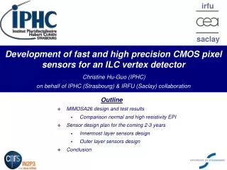
Development of MAPS for charged particle tracking: A fast readout architecture and its applications - IRFU (Saclay) & IPHC (Strasbourg) group -. Outline Achieved MAPS performances for charged particle tracking R&D for improving MAPS performances Fast readout Architecture

E N D
Development of MAPS for charged particle tracking:A fast readout architecture and its applications- IRFU (Saclay) & IPHC (Strasbourg) group - Outline Achieved MAPS performances for charged particle tracking R&D for improving MAPS performances Fast readout Architecture Applications and perspectives based on this architecture Conclusion Christine HU-GUO (IPHC-Strasbourg)
R.T. Development of MAPS for Charged Particle Tracking • In 1999, the IPHC CMOS sensor group proposed the first CMOS pixel sensor (MAPS) for future vertex detectors (ILC) • Numerous other applications of MAPS have emerged since then • ~10-15 HEP groups in the USA & Europe are presently active in MAPS R&D • Original aspect: integrated sensitive volume (EPI layer) and front-end readout electronics on the same substrate • Charge created in EPI, excess carries propagate thermally, collected by NWELL/PEPI , with help of reflection on boundaries with P-well and substrate (high doping) • Q = 80 e-h / µm signal < 1000 e- • Compact, flexible • EPI layer ~10–15 µm thick • thinning to ~30–40 µm permitted • Standard fabrication technology • cheap fast around • Room temperature operation • Attractive balance between granularity, material budget, radiation tolerance, read out speed and power dissipation • BUT • Very thin sensitive volume impact on signal magnitude (mV!) • Sensitive volume almost un-depleted impact on radiation tolerance & speed • Commercial fabrication (parameters) impact on sensing performances & radiation tolerance • NWELL used for charge collection restricted use of PMOS transistors IRFU - IPHC christine.hu@ires.in2p3.fr
Achieved Performances with Analogue Readout • MAPS provide excellent tracking performances • Detection efficiency ~100% • ENC ~10-15 e- • S/N > 20-30 (MPV) at room temperature • Single point resolution ~ µm, a function of pixel pitch • ~ 1 µm (10 µm pitch), ~ 3 µm (40 µm pitch) • Radiation tolerance: • Ionising radiation tolerance: O(1 M Rad) Mimosa15, (5 GeV e-, T -20°C, tint~180 µs) • Non ionising radiation tolerance: 2x10¹² Neq /cm2 (20 µm pitch) 1013 Neq /cm2 (10 µm pitch) • System integration • Thinning (via STAR collaboration at LBNL) ~50 µm, expected to ~30-40 µm • Edgeless dicing / stitching alleviate material budget of flex cable IRFU - IPHC christine.hu@ires.in2p3.fr
MIMOSA25 16x96 Pitch 20µm Improve MAPS Performance • Increase readout speed • Target value : read-out time 20 - 200 μs per image • Sensors organised in // columns read out + sparse data scan logic • Increase radiation tolerance • Ionising radiation: special layout, readout speed • Non ionising radiation: High resistivity sensitive volume faster charge collection • Exploration XFAB 0.6 µm techno: ~15 µm EPI, Vdd = 5 V, ~ O(103).cm • MIMOSA-25 (2008): tested with 106Ru () source before/after O(1 MeV) neutron irradiation • Exploration of a new VDSM technology with depleted substrate: • Project driven by CERN for SLHC trackers (also attractive for CBM, ILC and CLIC Vx Det.) • Using 3DIT to resorb most limitations specific to 2D MAPS • Coordinated by FermiLab • Talks: Y. Degerli , W. Dulinski on this meeting Talk: W. Dulinski on this meeting 20 μm pitch, + 20°C, 160 μs r.o. time ~0.3 / 1.3 / 3·1013neq/cm2 Tolerance improved by > 1 order of mag. Need to confirm det (uniformity !) with beam tests (CERN-SPS in May ’09) IRFU - IPHC christine.hu@ires.in2p3.fr
MIMOSA22 Pixel array 136 x 576 pitch 18.4 µm 128 discriminators SUZE-01 5-bit ADC 4-bit ADC Improve Readout Speed Digital Output Sensors • R&D organisation : 3 simultaneous prototyping lines • Architecture of pixel array organised in // columns read out: • Pixel: Pre-amp and CDS in each pixel • A/D conversion: 1 discriminator ending each column (offset compensation) • Power consumption v.s. Readout speed • Power Readout in a rolling shutter mode • Speed 1 row pixels are read out // • MIMOSA8 (2004), MIMOSA16 (2006), MIMOSA22 (2007/08) • Zero suppression circuit: SUZE-01 (2007) • Purpose: reduce the raw data flow of MAPS • Data compression factor ranging from 10 to 1000, depending on the hit density per frame • 4–5 bits ADCs (1000 ADC featuring 20×500 μm2 per sensor ! ) • potentially replacing each discriminator • sp < 2 μm (4 bits)1.7–1.6 μm (5 bits) for 20 μm pitch • Next step: interconnect ADC with pixel array IRFU - IPHC christine.hu@ires.in2p3.fr
0.64 mV 0.22 mV MIMOSA22 + SUZE-01 Test Results • MIMOSA22 (15 µm EPI) test results: 136 x 576 pixels + 128 column-level discriminators • SUZE-01: • Lab. test : • Design performances reproduced up to 1.15 × design read-out frequency (115 MHz at room Temp ): • No pattern encoding error, can handle > 100 hits/frame at rate ~200 ns per pixel row • Still to do : evaluate radiation tolerance (latch-up) of output memories, • Lab. test: • Temporal Noise: 0.64 mV 12 e- • FPN: 0.22 mV 4 e- • Beam test at CERN SPS • Threshold ~ 4 mV 6 σ noise • Detection Efficiency > 99.5% • Single point resolution < 4 µm • Fake rate < 10-4 IRFU - IPHC christine.hu@ires.in2p3.fr
MIMOSA26: 1st Sensor with Integrated Zero Suppression AMS C35B4: 0.35µm OPTO technology (15 µm EPI), submitted on Dec. 2008 Pixel array: 576 x 1152, pitch: 18.4 µm Active area: ~10.6 x 21.2 mm2 13.7 mm 1152 column-level discriminators Zero suppression logic Memory IP blocks 21.5 mm Current Ref. Bias DACs Readout controller JTAG controller Test blocksPLL, 8b/10b IRFU - IPHC christine.hu@ires.in2p3.fr
Vdd! PWR_On M4 M6 V_clp M3 Clp M9 M5 M10 M7 M8 Pdiff/Nwell Slct_Row M11 M2 Gr_node Nwell/Pepi Slct_Gr M12 M1 Pix_Out Gnd! Readout Chain: Pixel See Ref. A. Dorokhov et al., TWEPP-07 CERN-2007-007 proceeding pp. 423-427 Negative feedbackM5 & M7 low-pass filter Decrease the OP point variation due to process dispersion Self biased diode M5 Enclosed Layout Transistor Minimise leakage current CDS (Correlated Double Sampling): Clamping Suppress FPN Key element for charge collection Optimisation dimension & geometry Replace thick oxide surrounding Nwell diode thin oxide for tolerance to Ionising radiation • Output stage: SF (M10) • 1 column split into 36 groups Reduce SW cap. • Modified CS Amplifier: M2 input transistor , M3 & M4 load, M4 for biasing M3 • AC Gain improved • DC Gain & operating point unchanged Resistant to process variation ONLY NMOS transistors can be used, since any additional N-well used to host PMOS transistors would compete for charge collection with the sensing N-well diode IRFU - IPHC christine.hu@ires.in2p3.fr
Slct_Row Slct_Row Slct_Gr 16 pix Slct_Row Readout Chain: Pixel Slct_Row • 4 digital control signals per row: PWR_On, Slct_Row, Slct_Gr, Clp • Slct_Row (16xCK), PWR_On (2x16xCK), Slct_Gr (16x16xCK): power activate signals • Clp: signal for CDS (3xCK) • Power consumption: ~200 µW/pixel Slct_Row Slct_Gr 16 pix 18.4 µm Slct_Row Slct_Row Slct_Row Slct_Gr 16 pix Slct_Row Column –level discriminator RD CALIB LATCH IRFU - IPHC christine.hu@ires.in2p3.fr
Vclp_d RD REF1 RD RD REF2 Q CALIB LATCH To Pixel RD RD LATCH Vclp_d RD CALIB Q Readout Chain: Pixel + discriminator See Ref. Y. Degerli et al, IEEE, Trans. Nucl. Sci. vol.52, No. 6, pp. 3186-3193, Dec. 2005 • Discriminator design considerations: • Small input signal Offset compensated amplifier stage • Pitch: 16.4 µm (pixel pitch: 18.4 µm) • A/D conversion time = row read out time (~160 - 200 ns) • 1152 discriminators Low power consumption (~230 µW/discriminator) • Reference voltages (threshold) & clamping voltage are analogue signals which have to apply to 1152 discriminators • Need stable signals during "RD" & "CALIB" periods • Ex. RD (3 CK ~ 30 ns) • Need to drive ~2 cm long line • RC distribution line + successive charge rejections • Even an ideal voltage source CANNOT satisfy these requirements • 1152 discriminators are divided into 4 groups, 4 bias DAC • compensate process dispersions of discriminators Column-level Double Sampling (DS) reduce pixel to pixel dispersion (FPN) discriminator discriminator discriminator 1152 discriminators IRFU - IPHC christine.hu@ires.in2p3.fr
Readout Chain: zero suppression + memories ………… • Connected to column-level discriminators outputs • Zero suppression is based on row by row sparse data scan readout and organized in pipeline mode in three steps: Pixel Array Column 0 Column 1152 ………… Discriminators A/D A/D Core of the zero suppression ………… Sparse Data Scan (N states) Sparse Data Scan (N states) Sparse Data Scan (N states) Retaining M states per row (+ addresses) among 18 banks Memory 0 Memory 1 Serial transmission IRFU - IPHC christine.hu@ires.in2p3.fr
Readout Chain: zero suppression + memories • 1st step: • 1152 columns terminations 18 banks // scan • Based on a sparse data scan algorithm to find hit pixels (discriminator output = "1") • Up to 4 contiguous pixel signals above Vth will be encoded in a 2 bits state word following by address of the 1st pixel • Find up to N states with column addresses per bank ………… Column 0 Column 1152 ………… A/D A/D Core of the zero suppression ………… Sparse Data Scan (N states) Sparse Data Scan (N states) Sparse Data Scan (N states) Retaining M states per row (+ addresses) among 18 banks Memory 0 Memory 1 Serial transmission IRFU - IPHC christine.hu@ires.in2p3.fr
Readout Chain: zero suppression + memories …….… Row M-1 state Row M state Row M+1 state ……..….… HIT State Binary code 00 1 0 0 0 Row M 0 0 0 0 1 1 1 1 0 0 0 0 0 0 0 0 0 1 1 1 0 0 0 01 1 1 0 0 10 1 1 1 0 State 1 State 2 11 1 1 1 1 2 bits binary code Column address of the 1st pixel State: Column address of the 1st pixel+ 2 bits code IRFU - IPHC christine.hu@ires.in2p3.fr
Readout Chain: zero suppression + memories ………… • 2nd step: • Read out the outcomes of the 1st step in all banks and keep up to M states • Add row and bank addresses Column 0 Column 1152 ………… A/D A/D Core of the zero suppression ………… Sparse Data Scan (N states) Sparse Data Scan (N states) Sparse Data Scan (N states) Retaining M states per row (+ addresses) among 18 banks Memory 0 Memory 1 Serial transmission IRFU - IPHC christine.hu@ires.in2p3.fr
Readout Chain: zero suppression + memories ………… N, M, Memory capacity and Memory Read-out speed depend on hit density N = 6, M = 9, Memory ~ 40 Kbits, Nominal Read-out Freq.: 80 MHz • 3rd step: • Store the outcomes of the 2nd step to a memory • The memory is made of 2 IP's buffers continuous read-out • 1 buffer stores current frame, 1 buffer is read out previous frame • Serial transmission by LVDS pad ………… S0 ………… S1 ………… S17 Column 0 Column 1152 Column 0 Column 63 Column 0 Column 63 Column 0 Column 63 ………… A/D A/D Core of the zero suppression ………… Sparse Data Scan (N states) Sparse Data Scan (N states) Sparse Data Scan (N states) Retaining M states per row (+ addresses) among 18 banks Memory 0 Memory 1 Serial transmission IRFU - IPHC christine.hu@ires.in2p3.fr
Test MIMOSA26 • Mimosa26 returned from foundry on February 2009. • Extensive tests are going on in the laboratory. • Measured temporal noise = 0.6-0.7 mV and FPN = 0.3-0.4 mV for pixel array with its associated discriminators. • These values are equivalent to those obtained with Mimosa22. • Figures show measured results for one quarter of the matrix with column-level discriminators. The remaining three quarters of the matrix exhibit similar performances showing a good uniformity of the whole 576 x 1152 pixels with the 1152 discriminators • The characterization of Mimosa26 will be completed by the beam tests planned in Summer 2009 + yield evaluation IRFU - IPHC christine.hu@ires.in2p3.fr
y z x MIMOSA26 = Final Sensor for EUDET Telescope • EUDET supported by the European Union in the 6th Framework Programme • Provide to the scientific community an infrastructure aiming to support the detector R&D for the ILC • JRA1 (Joint Research Activity): High resolution pixel beam telescope • Two arms each equipped with three layers of pixel sensors (MIMOSA) • DUT is located between these arms and moveable via X-Y table • EUDET telescope: • High extrapolated resolution < 2 µm • Large sensor area ~ 2 cm2 • High read-out speed ~ 10 k frame/s • Hit density: up to 106 hits/s/cm2 Pixel Sensor MIMOSA26 13.7 mm (DUT) 21.5 mm Being Mounted on EUDET beam telescope IRFU - IPHC christine.hu@ires.in2p3.fr
Extension of MIMOSA-26 to STAR • Final HFT (Heavy Flavour Tracker) - PIXEL sensor : • MIMOSA-26 with active surface × 1.8 & improved radiation Tolerance • 1152 col. of 1024 pixels 1.1 million pixels • Pitch : 18.4 μm (21.2 x 18.8 mm2) • Integration time 200 μs • Design in Q2-Q4 2009 fab. end 2009 • 1st physics data expected in 2011/12 Pixel Vx Detector ~21.9 mm Inner Layer: 10 ladders Outer Layer: 30 ladders 10 sensors / ladder 21.5 mm STAR Detector Upgrade IRFU - IPHC christine.hu@ires.in2p3.fr
Extension of MIMOSA-26 to CBM/FAIR • Sensors for the Micro Vertex Detector (MVD) of the CBM H.I. fixed target expt : • 2 double-sided stations equipped with MIMOSA sensors • MIMOSA-26 with double-sided read-out r.o. speed ! • Active surface : 2 x 1152 columns of 256 pixels • 21.2 x 9.4 mm2 • tint. ~ 40 μs • < 25 μs in < 0.18 μm techno. • Prototyping until 2012 start of physics in 2013/14 IRFU - IPHC christine.hu@ires.in2p3.fr
Extension of MIMOSA-26 to ILC • Vertex detector at the ILC : 5 single layers & 3 double layers • Sensors for a vertex detector: • tint. ~ 25 μs (innermost layer) double-sided readout • tint. ~ 100 μs (outer layer) Single-sided readout • 2 μm (ADC ) < sp < 3 μm (discri.) • Pdiss < 0.1–1 W/cm2 × 1/50 duty cycle 5 single layers 3 double layers IRFU - IPHC christine.hu@ires.in2p3.fr
Conclusion • 2D MAPS have reached necessary prototyping maturity for real scale applications : • Beam telescopes allowing for sp ~ few μm & 106 particles/cm2/s • Vertex detectors requiring high resolution & very low material budget • The emergence of fabrication processes with depleted epitaxy / substrate opens the door to : • Substantial improvements in read-out speed and non-ionising radiation tolerance • "Large pitch" applications trackers (e.g. Super LHC ) • Translation to 3D integration technology : • Resorbs most limitations specific to 2D MAPS • T type & density, peripheral insensitive zone, combination of different CMOS processes • Offers an improved read-out speed : O(μs) ! • Many difficulties to overcome (ex. heat, power) • R&D is in progress 2009 important step for validation of this promising technology XFAB (19/5/2009): The full range of optical features will become available in the 0.35 um technology node next quarter. IRFU - IPHC christine.hu@ires.in2p3.fr