Download
1 / 21
220 likes | 406 Views
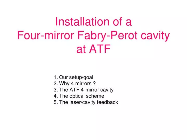
Installation of a Four-mirror Fabry-Perot cavity at ATF. Our setup/goal Why 4 mirrors ? The ATF 4-mirror cavity The optical scheme The laser/cavity feedback. French Japanese Collaboration. Araki-san. 2 steps R&D. STEP ONE: commissioning a 4-mirror cavity at ATF by end 2010.

E N D
Installation of aFour-mirror Fabry-Perot cavity at ATF Our setup/goal Why 4 mirrors ? The ATF 4-mirror cavity The optical scheme The laser/cavity feedback
French Japanese Collaboration Araki-san
2 steps R&D STEP ONE: commissioning a 4-mirror cavity at ATF by end 2010 STEP TWO: upgrade mirrors & laser power ~50W 200W Oscillator =0.2W, 1030nm Dt~0.2ps frep=178.5MHz Amplifier photonic fiberYb Doped 4-mirror Fabry-Perot cavity Gain~1000 10000 Numerical feedback ATF clock STEP ONE (end 2010) Withcavity laser/coupling ~50% Power_cavity~25kW ~75g/bunch crossing~5 E9 g/s (Emax=28MeV) STEP TWO (curren-end 2011 ?) With cavity laser/coupling ~50% Power_cavity~500kW ~3000g/bunch crossing~2 E11g/s Goal: to reach the MW average power
Why a non planar four-mirror cavity ? Laser input e- beam 2-mirrors& small laser spot unstableresonator Stable solution: 4 mirrorcavityas in Femto laser technology BUT astigmatic & linearlypolarised eigen-modeswhich are instable because of vibrationsat very high finesse (AO48(2009)6651) • Non-planar 4-mirror cavity • Stable & circularly polarised eigenmodes (AO48(2009)6651) • New feedback technics with this geometry (Honda,OC282(2009)3108)
Prototype of nonlanar 4 mirrors resonator (low finesse) • Check the general astigmatism mode shape/propagation (Arnaud,Bell Syst. Tech. ( 1970)2311) • ok Ellipse intensity profile ‘turning’ Kogelnik, Apl. Opt. 8(1969)1687 50cm
2 spherical mirrors 2 flat mirrors Non planar 4-mirror cavity for ATF ATF beam pipe: 5mm slit… Angle laser / e- beam= 8° ATF e-beam laser/beam Interaction point Injection laser
Mirror positioning system 12 Encapsulated Motors 2 spherical mirrors e- Mounting in class 10 room laser Invar base to ensurelength stability 2 flat mirrors
OVERALL DESIGN PRINCIPLE θx actuator Gimbal mountsθx θy ± 10 mrad Encapsulatedcommercialstepper motor bellow θy translation Z actuators ~10nm minimum steps2mm range translation : 3 balls on guide rail and plan
Cavity round-trip -ATF clockmatchingdonewith 1 z translation motor & 1 annularpiezoismountedinside one flat mirrormount Place forATF beam pipe Mirror mount troncatedto decrease incidentangle : 8°
Vacuum vessel for ATF Ultra high vacuum wires for the12 motors and the piezo Vaccuum once installedat ATF: ~6.5x10⁻⁸mbar
Implementationat ATF Assumed ATF Beam Line Pulse Motor Port for Up-Down Move Pulse Motor Port for Horizontal Move From Hirotaka-san Funahasi-san’s ATF micrometric table mount system
The optical scheme Phase modulatorneeded for the feedback • Signal reflected by the cavity used to build the laser/cavity feedback signal: • interference between the modulated incident laser beam AND the leackage on the beam circulating inside the cavity Feedback system
Numericalelectronic for:laser-cavity Pound-Drever-Hall feedbackcavity-ATF clock feedback Clk = 100 MHz 8x ADC 14 bits 8x DAC 14 bits => Filtering => 18 bits / 400 kHz FPGA Virtex II (Virtex IV) Rétroaction on laser frequency 13
The laser amplification R&D We use Ytterbium dopedphotonic cristal fiber as amplifier • We obtained 200W but spot was not stable • We fix the power to ~50W to get stable laser beam • Thermal control issues to be solved before increasing power • Also damage protection issues are not easy to solve at very high power (we broke many fibers…) • Recent publication shows 800W average power (11µJ/pulse)with same technics (Limpert,OL35(2010)94) • but we need long term stability and reliability… • thechnological R&D Ø core = 40 µm Ø cladding = 200 µm Towardcavity laser Fiberamplifier 14
ATF 4-mirror 2-mirror
And aligned in ATF ring 29th july: after 3 days ready to install the experiment
Status • Laser-cavity-ATF_clock are locked together • Still some DAQ code to be written but we should start to try to produce our first g rays next week • Progress in parallel • Increase laser power R&D (will restart in 2011) • Use sapphire substrates for the cavity mirrors to prevent thermal load effects (started last month)
Summary • There is now a new 4-mirror fabry-perot cavities in ATF to contribute to a global R&D effort to reach the MW average power level 1 cavitypulsed2-mirrors 4-mirror pulsedcavity 2 cavitiescwlaser-wire The new cavity has 4 mirrors and is non-planar to match requests of futur Compton e+ polarised sources or compact X-ray machines