Download
1 / 29
290 likes | 373 Views
Single-Cavity Module Installation at MuCool Test Area. Yağmur Torun MICE Collaboration Meeting February 15, 2013. MTA 201-MHz Program Overview (Surface treatment, NF channel, MICE). 201-MHz MICE prototype cavity with SRF-like surface treatment (EP, HP rinse)

E N D
Single-Cavity Module Installationat MuCool Test Area Yağmur Torun MICE Collaboration Meeting February 15, 2013
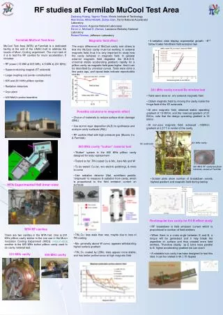
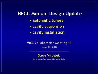
MTA 201-MHz Program Overview(Surface treatment, NF channel, MICE) Y. Torun | MICE cm35 • 201-MHz MICE prototype cavity with SRF-like surface treatment (EP, HP rinse) • Conditioned to design gradient quickly • Demonstrated operation with curved Be windows • Somewhat reduced performance in fringe field of solenoid • No surface damage seen on cavity interior • Some evidence for sparking in the coupler • New design has been implemented • Radiation output measured (MICE detector backgrounds) • Future • Install/operate single-cavity vessel • Large diameter magnet (“coupling coil”) needed for field configuration closer to MICE/cooling channel
201-MHz Single-Cavity Module Y. Torun | MICE cm35 • MICE cavity in vacuum vessel for MTA test • Components • 1st MICE cavity EP’ed and now at Fermilab • Be windows ready • Tuner forks built • Ready for fabrication of new couplers
201-MHz Single-Cavity Module Y. Torun | MICE cm35 • Assembly/integration • Cavity and vessel at Lab-6 • Clean room prepared • Plan in place for handling and transport (R. Schultz, J. Volk) • Assembly fixture designed (A. DeMello) • Tuner control bench tested (P. Hanlet) • Expect operation Summer 2013 • beam test also under consideration • Ultimately will be tested with the first Coupling Coil Magnet • Requires 6-month MTA shutdown
Current configuration • Original prototype cavity still in the hall • was lifted onto platform during long shutdown with shield wall out • using temporary forklift • No vacuum vessel, air outside • end-plates for support • Couplers already removed • one cut up for inspection • To be lifted off platform • with new gantry crane • span limited by entry maze • and rolled out through labyrinth on casters • Rails will be reused for new module • Be windows will be transferred to new cavity Y. Torun | MICE cm35
Next -- Single-Cavity Vessel Y. Torun | MICE cm35
Final layout -- RFCClite Y. Torun | MICE cm35
Cavity in Lab-6 Y. Torun | MICE cm35
Vacuum Vessel in Lab-6 Y. Torun | MICE cm35
Module Transport Y. Torun | MICE cm35 • Will bring into MTA hall through labyrinth • Vessel with heavily ribbed doors too wide for labyrinth • Will remove and roll in doors separately • Put on thin cover plate to keep module interior clean • Module on stand too tall for clean room and labyrinth • New “transport” stand is 10” shorter • Tight fit – checked with laser scan data
MTA Hall Layout Y. Torun | MICE cm35
Laser scan data Y. Torun | MICE cm35
Through the Maze Y. Torun | MICE cm35
Cover Plate Transport Y. Torun | MICE cm35
Lab 6 Clean Room Y. Torun | MICE cm35 • Once doors removed & transport stand installed • Cavity installation – Vertical • In Lab 6 clean room – Class 100 • Insertion picture shown in clean room is old design • New design (A. DeMello) hot off the press • All mechanical assembly and RF testing in clean room
Cavity handling Y. Torun | MICE cm35 Detailed procedure available from LBNL
Tuner installation Initial concept – horizontal layout Y. Torun | MICE cm35
Cavity installation • Vertical layout selected • Smaller footprint better suited to available clean room space • Similar to MICE RFCC • Simplified (one-sided) Y. Torun | MICE cm35
Insertion Fixture in Clean Room Y. Torun | MICE cm35
Assembly in MTA Hall Y. Torun | MICE cm35 • Remove transport stand, install operational stand • In MTA Clean Room • Install doors • RF Couplers • Other vacuum hardware
Put on doors in MTA clean room Y. Torun | MICE cm35
Rough schedule Y. Torun | MICE cm35
Rough schedule Y. Torun | MICE cm35
Rough schedule Y. Torun | MICE cm35
Other issues • Couplers • preferable to test/condition before installation on cavity • couplers for prototype were conditioned at SNS on custom stand • looking into locating leftover parts to it back together (R. Rimmer) • or designing a new stand • Diagnostics • will build top plate with RF and vacuum pickups • acoustic sensors under test may be useful (P. Lane, P. Snopok) • RF controls • plan in place to upgrade Linac 201-MHz station (R. Pasquinelli) Y. Torun | MICE cm35
Outlook • On track for results from operation of single-cavity module at MTA by cm37 • tight schedule and lots of work to do • resource availability critical • Installation will provide valuable experience for MICE RFCC module assembly • There may be an opportunity to test MICE RF phase measurement concept Y. Torun | MICE cm35
Credits • Most mechanical engineering material from Ryan Schultz (FNAL) & Allan DeMello (LBNL) Y. Torun | MICE cm35