Download
1 / 16
160 likes | 163 Views
Pierpaolo Valerio. Noise performances of MAPS and Hybrid Detector technology. Motivations. Brief comparison of the two main technologies in radiation detectors, trying to analyze advantages and disadvantages of both. Particular attention was taken in referring to CLIC specifications.

E N D
Pierpaolo Valerio Noise performances of MAPS and Hybrid Detector technology
Motivations Brief comparison of the two main technologies in radiation detectors, trying to analyze advantages and disadvantages of both. Particular attention was taken in referring to CLIC specifications. The study is a work in progress and it is by no means complete. Most of the data comes from a theoretical analysis, but they were checked against literature when possible.
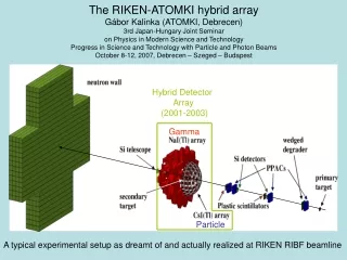
Hybrid Detectors Hybrid detectors are detectors made of two separate components: a converting material (50 um Silicon for CLIC) and an ASIC implementing the readout electronics The two parts are connected together with bump bonding (flip chip).
MAPS MAPS (Monolithic Active Pixel Sensors) integrates the electronics into the active sensor, providing a fully-built detector with only one substrate. The charge produced by the incoming particle is collected by one or more diodes due to electron diffusion in the active substrate. The doping gradient generates a potential barrier that stops electrons from entering the upper or lower substrates (more heavily doped). 2-20um
MAPS The principle of MAPS makes it possible to use only n-MOSFETs to build the electronics, so no complex (such as an active leakage compensation) or digital circuit can be designed. The most used design is a 3 transistor reset and source follower configuration. It is possible to implement more complex structures with n-MOS amplifiers.
MAPS The readout is carried out by row. The detector diodes need periodic resets to compensate for leakage current. Fill factor is 100% for MIPs (Minimum Ionizing Particles).
Advantages and Drawbacks Pros of MAPS approach over Hybrid Detectors: • Higher integration, less mass, small pixels • No flip chip means higher yields, lower costs • Potentially lower noise Cons: • Less versatility (only silicon substrate) • Simpler electronics, preventing implementation of photon counting or any digital circuit in the pixels • No accurate timestamp information
Assumptions on the models Input capacitance: Power consumption per area is constant:
Noise contributions (HD) The main contributions to the equivalent noise charge are: • Thermal Noise • Flicker noise • Shot noise due to the sensor current Array non-uniformity is corrected by pixel calibration.
Noise contributions (MAPS) The main contributions to the equivalent noise charge are: • Thermal Noise • Flicker noise • Shot noise due to the leakage current • Reset noise where:
Correlated Double Sampling Contributions due to Flicker noise, reset noise and Fixed Pattern Noise can be effectively cancelled by using CDS: measuring the output immediately after the reset and again at the end of the integration period. Other noise contributions are increased by a factor of √2, but the reset noise is dominant otherwise. Without CDS a software calibration can still compensate for the FPN. This approach is not necessary with Hybrid Detector, as the detection is achieved comparing the signal to a threshold which is higher than noise level.
Noise (changing readout time) ENC (e-) Upper plot: Noise contributions for Hybrid Detectors. Data are taken from the 55um pitch Medipix3 (in particular Cin = 18fF). Lower plots: Total noise for MAPS (left) and noise contributions to it (right). Data are taken from publications on the MIMOSA-26 chip (18.4um pitch, 10fF diode capacitance). Green: Total noise Blue: Thermal noise Red: Flicker noise Yellow: Shot noise Shaping time (s) ENC (e-) ENC (e-) Green: Flicker noise Blue: Reset noise Red: Thermal noise Yellow: Shot noise Blue: Noise without CDS Red: Noise with CDS Integration time (s) Integration time (s)
Noise (changing pixel size) ENC (e-) Upper plot: Noise contributions for Hybrid Detectors. Plots assume a shaping time of 100ns, as it produces a jitter of less than 10ns (more on this later). Values for the input capacitance are extrapolated form the data of Medipix3 Lower plots: Total noise for MAPS (left) and noise contributions to it (right). Data are taken from publications on the MIMOSA-26 chip (the integration time produces a negligible change). Green: Total noise Blue: Thermal noise Red: Flicker noise Yellow: Shot noise Pixel side (um) ENC (e-) ENC (e-) Green: Flicker noise Blue: Reset noise Red: Thermal noise Yellow: Shot noise Blue: Noise without CDS Red: Noise with CDS Pixel side (um) Pixel side (um)
Other effects In MAPS sensors the collection of the charge produced by incoming particles is due to diffusion, without an electric field. This leads to an higher recombination rate in the sensitive material, so the “collection rate” should be analyzed. Pixel geometries can vary: in particular, MAPS with multiple diodes per pixels can substantially reduce charge sharing between adjacent pixels
Timing Information Hybrid Detectors have the possibility of acquiring a time stamp of the events. The jitter relates to the noise and the shaping time according to this equation: Data are extrapolated from the Medipix3 analysis. The requirement is less than 10ns, so it can be achieved for shaping time less than 1us. Charge sharing is not included in this model. Jitter (s) Red: 25um pixels Blue: 50um pixels Yellow: 100um pixels Shaping time (s)
Conclusions Both architectures have different strengths and disadvantages The possibility to have a timestamp measurement is a critical feature of Hybrid Detectors. This feature was already demonstrated with other chips developed at CERN. On the other hand MAPS have lower noise and higher scalability.