Download
1 / 25
250 likes | 329 Views
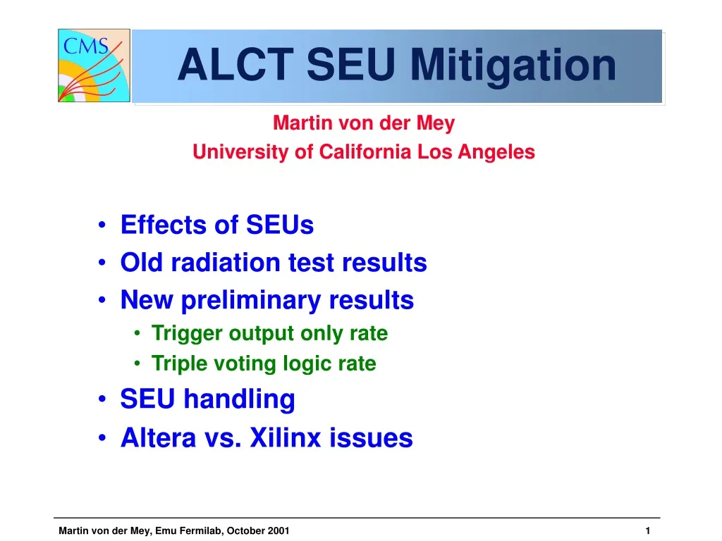
ALCT SEU Mitigation. Martin von der Mey University of California Los Angeles Effects of SEUs Old radiation test results New preliminary results Trigger output only rate Triple voting logic rate SEU handling Altera vs. Xilinx issues. ALCT Status.

E N D
ALCT SEU Mitigation • Martin von der Mey • University of California Los Angeles • Effects of SEUs • Old radiation test results • New preliminary results • Trigger output only rate • Triple voting logic rate • SEU handling • Altera vs. Xilinx issues
ALCT Status • ALCT is the CSC anode trigger and readout board (Anode Local Charged Track) • ALCT2000 prototype worked but… • FPGAs suffered frequent “upsets” (program changes) with neutron radiation • Reload of FPGAs took “long” 150ms • Re-design has suffered several personnel changes • On-chamber electronics needs to be delivered well before installation • Therefore, ALCT schedule is now a critical path item for Emu.
ALCT Functions • Inputs discriminated signals from AFEB front-end boards, provides AFEB support: • Distributes power and shut-down signals. • Sets and reads back discriminator thresholds. • Creates and distributes amplifier/discriminator test pulses. • Delay/translator ASIC on input does time alignment with bunch crossings. • Searches for muon patterns in anode signals. If found, sends information to Trigger Motherboard. • Records input and output signals at 40 MHz (up to 672 channels/board) in case of Level 1 trigger. • Other support functions: • Creates and distributes test pulses for test strips. • Controls delay ASICs with 2ns precision (0-30 ns setting). • Reads board currents, voltages, and temperature.
ALCT2001 Modifications • Radiation-related • Hardware change from Altera to Xilinx FPGAs – loads faster. Needs firmware change from AHDL to Verilog. (Alex) • Hard reset signal from TMB starts reload of FPGAs from rad-hard EEPROMs. • Design improvements • Replace multiple Ball-Grid Arrays (BGA) by single chip on mezzanine card. • XCV600E, 1000E, or 1600E (identical packages). In moment we use XCV600E. • 40-to-80 MHz multiplexors required for single-chip design. Reduce number of cables. • 4 control/output connectors reduced to 2. • Robustness, testing • Very stiff mezzanine card holding ball-grid array. • Delay chips now allow pattern loading in order to test critical input ball grid array connections.
Main board for 384-ch type New ALCT Boards Power, computer connectors 80 MHz SCSI outputs (to Trigger Motherboard) Xilinx mezzanine card Delay/ buffer ASICs, 2:1 bus multiplexers (other side) Input signal connectors Analog section: test pulse generator, AFEB power, ADCs, DACs (other side)
ALCT Production Testing • FPGA self-test software exists • Patterns loaded into delay chips check connections to FPGAs • Full test requires external connections: • FPGA loaded from PC // port • Testing program drives outputs and looks at inputs at 40 MHz • Two data paths to test: • Input side AFEB-ALCT path • Output side ALCT-TMB path • Timing tested with delay curves • Boards tested before and after baking in oven • Tests planned at FNAL
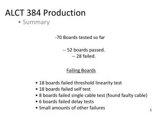
Present Status • Prototype batch of 6 ALCT2001-384 boards and mezzanine boards produced • Debugging of these boards is ongoing • Smoke tests passed on all 6 ALCT board. • Slow Control functions are now fully debugged. • Virtex FPGAs successfully downloaded and project is “alive”, registers can be written and read back. Patterns and delay written to Delay ASICs and verified reading out FIFO in Virtex FPGA. • Layout: ALCT-672 is complete, ALCT-288 is ongoing • Improved cable tester produced (80 MHz, 12 meters maximum), new Tyco cable has been delivered and are being tested. • Production test board – close to layout stage. Test firmware needs development. Improvements have been added, e.g. FIFOs and fine (0.25ns) delays. • DAQ readout through TMB: board in layout stage, firmware development proceeding (adapted from previous TMB99). • The TMB functions have still to be included into the firmware. • Known simple design mods required/desired: • Adopt known rad-tolerant regulator for test pulse circuit. • Move a couple of jumpers and test points out from under mezzanine card.
Some Test Results • Thresholds: • (ADC-DAC) +2*Channel vs DAC setting. • Essentially perfect behavior Virtex loading time (38ms). Virtex power about 1 watt.
Near-term ALCT Schedule • Sept: Finish debugging of first 6 boards and self-test firmware • Sept. 26: first radiation test • October: second radiation test (?) • October: Finish radiation tests and validation • Nov. 20: Batch of 10 ALCT-384 shipped • ~Dec 1: Production approval at ESR • Jan. 2, 2002: Batch of 20 ALCT-384 shipped • Jan. 7, 2002: Batch of 7 ALCT-672 shipped • Validation appears to be the major bottleneck • In 2002, production/testing rate is not a problem (catch up with chamber production/testing rapidly)
ALCT Development Team • Done: ALCT2001-384 schematics and layout by Sedov and Iatsioura (PNPI at UCLA) Xilinx mezzanine card schematics and layout by Iatsioura and Kan (PNPI) ALCT2001-672 schematics and layout by Kan “Xblaster” parallel-to-JTAG LVDS, by Kan and Shi • Schematics and layout for ALCT-288ch, and other mods: Kan • Firmware design/simulations: Madorsky/von der Mey (previously JK, Razmyslovitch, Zhmakin) • Production supervision of ALCTs Iatsioura • Production testing of ALCT and later TMB Zhmakin (PNPI at FNAL) and Lindgren • Radiation testing Martin von der Mey • Trigger Motherboard (DAQ readout) Design and firmware by JK Outsourced layout and production
Effect of an ALCT SEU • Much-overlooked good stuff • Is a random effect • Uncorrelated between muon stations • Doesn’t affect CLCT or cathode data • A chamber is not “dead” • An inefficiency for the trigger • Is mainly an issue for ME1/1 trigger efficiency • Other stations: rates down by 4 or much more • Much-overlooked bad stuff • Puts ALCT into an unknown state
SEU Measurements • Calculations: SEU s = (2.3+-0.5)*10-9 cm2 per chip L = 4*104/cm2/s flux estimate ME1/1 x3 SEU s*L = 9.2*10-5/s rate per chip x3 SEU s*L = 3.7*10-4/s rate per board (4 chips) x3 • Refresh every 40 sec: 0.15s/40s = 0.37% refresh deadtime 0.7% SEU-affected boards in ME1/1 <0.18% SEU in other stations • Note - SEUs are better than deadtime: SEUs are uncorrelated between muon stations Muons still leave cathode LCTs for both trigger & DAQ Deadtime is incurred for all of CMS if synch’ed • Any bit errors during self-test
Old SEU Measurements • LCT chip measurements : • Separate out Trigger errors from DAQ hit readout errors • have/don’t have trigger, or • wire group wrong, or • pattern or accelerator bits wrong • Non-redundant logic trigger errors: • 25% of previous measurement • Triple-redundant logic trigger errors: • 3.3% of previous measurement
New Refresh Calc’s • Non-redundant logic: s *L= 9*10-5/s rate per board (4 chips) x3 refresh every 80 sec 0.15s/80s = 0.19% refresh deadtime 0.5% SEU-affected boards in ME1/1 <0.125% SEU in other stations • Triple-redundant logic: s *L= 1.2*10-5/s rate per board (4 chips) x3 refresh every 200 sec 0.15s/200s = 0.07% refresh deadtime 0.24% SEU-affected boards in ME1/1 <0.06% SEU in other stations • Without x3 rate safety factor, it’s about 600s between refresh, and 0.02% deadtime
SEU Handling • Triple-redundant logic gives early warning • single upset is okay (warning) • double upset zeroes out the ALCT trigger result • active protocol added: CLCT can poll ALCT for upsets, or ALCT can volunteer upsets • Periodic self-tests cycle all of the trigger logic • plus the Concentrator • 10 Hz of 88 us testing allowed by pixel refresh • active protocol: CLCT initiates self-tests in smooth way • Hooks are there for several options: • centralized periodic refresh • record number, time of SEUs via data path to DAQMB • report SEU to central trigger control (but how from CLCT?) • autonomous but recorded refresh
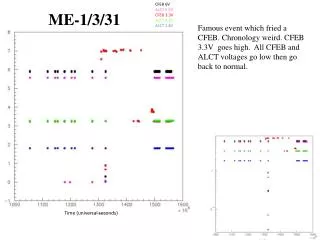
New results • Radiation tests at UC Davis… • Cyclotron with proton beam energy 63.3 MeV
Virtex chip • Radiation results shows small improvements to before… • Mean lies at 65.2 Rad compared to 59.2 Rad before… • The main improvement (factor 5) comes due to combination of 5 chips • (1 concentrator and 4 LCT chips into 1). • SEU Sigma = 2.1*10^-9 cm^2
Virtex Eprom • Move board to irradiate Eproms • After radiation verify logic in Eprom using • Xilinx Foundation • Result : • Radiated Eprom for 5 minutes at • 100 pA (0.70 kRad) • 500 pA (3.48 kRad) • 1000 pA (7.04 kRad) • Check logic using Xilinx Foundation • No errors were found….No problem for LHC…
Bus multiplexor • Irradiated bus multiplexors with 1nA for 5 minutes • 14.47 kRad beam current • 7.05 kRad beam current • Used Alex program. Write and Read Delay • Lines… • Results : • No errors found…
Delay ASICs • Move to Delay ASICs • Irradiate 4 ASICs with 1 nA beam. • While irradiation write and read delay • Lines… • After 20.3 kRad no error found… • As expected no problems with the Delay ASICs • are expected
Slow Control FPGA • Irradiate Slow Control • FPGA… • With… • 50 pA proton beam current. • 100 pA beam current • 500 pA beam current. • Flat distribution…Mean is • 293.3 Rad…much higher • than for the Virtex FPGA • No problem to expect for • Spartan XL FPGA
Other Issues • Triple-logic not possible in some places • for voting logic itself • Concentrator FPGA - too many miscellaneous I/O and too many possible states • Result of SEU is unpredictable (haywire?) • Minimizing rate of SEUs is good, but • Smooth detection and handling is MORE important • Altera 20K series may have different (lower?) SEU cross-section • A rough estimation might be gotten with demux test board
Xilinx vs. Altera: Fact and Fiction • 3 claims from the ESR report: • Xilinx loads faster • Xilinx is more radiation tolerant • Xilinx may be reloadable by section • Reality: • We have seen NO evidence that Xilinx is more radiation tolerant. • ALCT logic and test procedure were both significantly different from CFEB • Very unlikely that Xilinx can be reloaded in section • Also problematic to read back and check configuration - get SEUs during read process (Durkin) • Only verified advantage of Xilinx: faster loading • 5ms vs 150ms
More on Xilinx vs Altera • Impossible to use Xilinx flat packs (I/O count too small) • BGA assembly, testing, and reliability issues • Design consideration: can refresh from CLCT directly • eliminates EPROMs on ALCT board • will be ~120ms for Xilinx or Altera • Conversion requires language change • Mainly AHDL to VHDL, or to Verilog HDL • Expect 3-4 month conversion time • Expect ~2 months of radiation tests