Download
1 / 14
150 likes | 315 Views
MIE313 Design of Mechanical Components -- Spring 2002. Instructor: Sundar Krishnamurty Office: ELAB 207B Phone: 545-0297 Email: skrishna@ecs.umass.edu Office Hours: TH 1-2:30pm TA: Tom Kimerling Homepage: TBA. Course Outline.

E N D
MIE313 Design of Mechanical Components -- Spring 2002 Instructor: Sundar Krishnamurty Office: ELAB 207B Phone: 545-0297 Email: skrishna@ecs.umass.edu Office Hours: TH 1-2:30pm TA: Tom Kimerling Homepage: TBA
Course Outline • To learn and apply basic mechanical analysis techniques (Statics, Dynamics, Strength of Materials) • To develop insight from analysis & use it in design • To learn to design to fulfill specific functional requirements (Engin113, MIE213) • To learn solid modeling and finite element analysis computer skills (LAB) • To reinforce (semester-long group Design and Analysis Project) • communication (written, oral, and graphical) • cooperative problem solving • project management skills
Mechanics Solid Mechanics Fluid Mechanics Statics Dynamics Kinematics Dynamics Course Overview • Review: Solid mechanics, work, energy, and power conservation (Ch. 1&2)
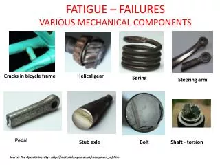
Text Book & Topics • Robert C. Juvinall and Kurt M. Marshek, Fundamentals of Machine Component Design, 3rd Edition, John Wiley & Sons • Safety Considerations • Load Analysis • Stress-Strain Analysis • Failure Theories and Modes • Finite Element Analysis • Pro Mechanica
Related Topics • Force Analysis (FBD) • Stresses and Strains • Fatigue Analysis • Design Evaluation • Strength of Material • Component design • Shafts
Grade Distribution • Homework 5 % • Quizzes & Class Participation 10% • Midterm Exam 15% • Final Exam 20% -------------- • FEA Homework 5 % • Force Model & Solid Model Report 10% • Project Baseline Analysis Report 15% • Final Project Report 20%
Related Information • Academic Honesty Policy: • http://www.ecs.umass.edu/mie/hon97.html • Pro Engineer and Pro Mechanica: • All students expected to have working knowledge of Pro E • All Students are required to attend a 2 hour training session on Pro Mechanica
Project Teams • Teams of 3 (and 4) • Project Groups • Goal: • To discuss, decide, and to do real work together • Rotating Leadership • Studies have shown that rotating leadership assignments in semester-long projects works well • Every member has an opportunity to be the leader for at least one reports
Project Selection Criteria • Design Against Failure • Geometry Complexity • Load Estimation • Operating Conditions • Material Properties • Functional Behaviors: • Elastostatic analysis • thermal analysis • Buckling & Free vibration
Project Information • Goal: • Product Redesign requiring design, analysis, and evaluation of one or more special purpose parts • Project Proposal • Force Model & Solid Model Report • Analysis Report • Final Report Sideview Mirror
Project Evaluation • All reports will be evaluated based on: • Substance: Quality of contents and quality of drawings • Style: Presentation of materials in an integrated manner that is easy to read with no spelling, grammar, or, other errors
Project Proposal • Two-pages to include: • Member names and rotating leadership assignment • A brief overview of your design describing: • General functions, operating conditions, and overall objectives of your project • A sketch of the Actual Part or subassembly • Project Timeline with task schedule
Force Model & Solid Model Report • Group report with a leader clearly identified • Suggested topics: • Introduction • Objectives • Plan of Work • Force Model • FBD based Force Analysis • Solid Models of critical components • All figures should be numbered and have figure captions • Conclusion
Project Analysis Report • Group report with a leader clearly identified • Improved Solid Model Report • PLUS: • FEA of critical components • Discuss in detail your simplifications in the context of your design objectives • Clearly detail load conditions • Discuss and kinematic constraints • Validation of your results using simplified hand calculations • Conclusion