Download
1 / 26
610 likes | 1.32k Views
Mechanical Design of Process Equipment. 13.3. FUNDAMENTAL PRINCIPLES AND EQUATIONS. 13.3.1. Principal stresses 13.3.2. Theories of failure 13.3.3. Elastic stability 13.3.4. Membrane stresses in shells of revolution 13.3.5. Flat plates 13.3.6. Dilation of vessels 13.3.7. Secondary stresses.

E N D
13.3. FUNDAMENTAL PRINCIPLES AND EQUATIONS 13.3.1. Principal stresses 13.3.2. Theories of failure 13.3.3. Elastic stability 13.3.4. Membrane stresses in shells of revolution 13.3.5. Flat plates 13.3.6. Dilation of vessels 13.3.7. Secondary stresses
13.3.1. Principal stresses • are the maximum values of the normal stresses at the point; which act on planes on which the shear stress is zero • In a two-dimensional stress system, the principal stresses at any point are related to the normal stresses in the x and y directions x and y and the shear stress xy at the point by the following equation: Maximum shear stress = 1/2 (1 - 2) Two-dimensional stress system
13.3.2. Theories of failure Maximum principal stress theory Maximum shear stress theory Maximum strain energy theory
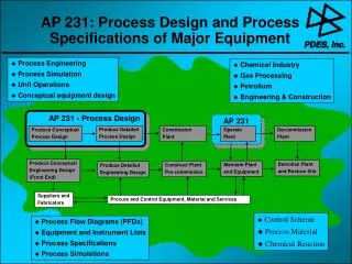
13.4. GENERAL DESIGN CONSIDERATIONS: PRESSURE VESSELS 13.4.1. Design pressure 13.4.2. Design temperature 13.4.3. Materials 13.4.4. Design stress (nominal design strength) 13.4.5. Welded joint efficiency, and construction categories 13.4.6. Corrosion allowance 13.4.7. Design loads 13.4.8. Minimum practical wall thickness
13.4.1 Design Pressure • For vessels under internal pressure, the design pressure is normally taken as the pressure at which the relief device is set. This will normally be 5 to 10 per cent above the normal working pressure. The hydrostatic pressure in the base of the column should be added to the operating pressure, if significant • Vessels subject to external pressure should be designed to resist the maximum differential pressure that is likely to occur in service. • Vessels likely to be subjected to vacuum should be designed for a full negative pressure of 1 bar, unless fitted with an effective, and reliable, vacuum breaker.
13.4.2 Design Temperature • The strength of metals decreases with increasing temperature so the maximum allowable design stress will depend on the material temperature. • The design temperature at which the design stress is evaluated should be taken as the maximum working temperature of the material, with due allowance for any uncertainty involved in predicting vessel wall temperatures.
13.4.3 Material • Pressure vessels are constructed from plain carbon steels, low and high alloy steels, other alloys, clad plate, and reinforced plastics. • Selection of a suitable material must take into account the suitability of the material for fabrication (particularly welding) as well as the compatibility of the material with the process environment. • The pressure vessel design codes and standards include lists of acceptable materials; in accordance with the appropriate material standards.
13.4.4 Design Stress (nominal design strength) • It is necessary to decide a value for the maximum allowable stress (nominal design strength) that can be accepted in the material of construction. • Applying a suitable “design stress factor” (factor of safety) to the maximum stress that the material could be expected to withstand without failure under standard test conditions. • The design stress factor allows for any uncertainty in the design methods, the loading, the quality of the materials, and the workmanship.
13.4.5 Welded Joint Efficiency • The strength of a welded joint will depend on the type of joint and the quality of the welding. • The soundness of welds is checked by visual inspection and by non-destructive testing (radiography). • Taking the factor as 1.0 implies that the joint is equally as strong as the virgin plate; this is achieved by radiographing the complete weld length, and cutting out and remaking any defects. • The designer must balance any cost savings on inspection and fabrication against the increased cost of materials.
13.4.6 Corrosion Allowance • The “corrosion allowance” is the additional thickness of metal added to allow for material lost by corrosion and erosion, or scaling. • The allowance to be used should be agreed between the customer and manufacturer. • The allowance should be based on experience with the material of construction under similar service conditions to those for the proposed design. • For carbon and low-alloy steels, where severe corrosion is not expected, a minimum allowance of 2.0 mm should be used; where more severe conditions are anticipated this should be increased to 4.0 mm. Most design codes and standards specify a minimum allowance of 1.0 mm.
13.4.7 Design Load • A structure must be designed to resist gross plastic deformation and collapse under all the conditions of loading. • The loads can be classified as major loads, that must always be considered in vessel design, and subsidiary loads. • Formal stress analysis to determine the effect of the subsidiary loads is only required in the codes and standards where it is not possible to demonstrate the adequacy of the proposed design by other means; such as by comparison with the known behaviour of existing vessels.
Major loads Design pressure: including any significant static head of liquid. Maximum weight of the vessel and contents, under operating conditions. Maximum weight of the vessel and contents under the hydraulic test conditions. Wind loads. Earthquake (seismic) loads. Loads supported by, or reacting on, the vessel.
Subsidiary loads Local stresses caused by supports, internal structures and connecting pipes. Shock loads caused by water hammer, or by surging of the vessel contents. Bending moments caused by eccentricity of the centre of the working pressure relative to the neutral axis of the vessel. Stresses due to temperature differences and differences in the coefficient expansion of materials. Loads caused by fluctuations in temperature and pressure.
R e m a r k • A vessel will not be subject to all these loads simultaneously. • The designer must determine what combination of possible loads gives the worst situation, and design for that loading condition.
13.4.8 Minimum Practical Wall Thickness • There will be a minimum wall thickness required to ensure that any vessel is sufficiently rigid to withstand its own weight, and any incidental loads. • As a general guide the wall thickness of any vessel should not be less than the values given below; the values include a corrosion allowance of 2 mm: