Download
1 / 43
440 likes | 623 Views
10 th IHHA Conference February 4 - 6, 2013, New Delhi HIGH HORSE POWER LOCOMOTIVES FOR DEDICATED FREIGHT CORRIDOR. Name of Presenter- Sandeep Srivastava Session – M1 Date of presentation - 04.02.13. Name: Sandeep Srivastava

E N D
10th IHHA Conference February 4 - 6, 2013, New DelhiHIGH HORSE POWER LOCOMOTIVES FOR DEDICATED FREIGHT CORRIDOR Name of Presenter- SandeepSrivastava Session – M1 Date of presentation - 04.02.13
Name: SandeepSrivastava Present: Research Designs and Standard Organisation Lucknow Job Profile: Issues related to reliability and maintenance of GTO based three phase drive electric locomotives Development / acquisition of new technology and locomotives Experience: 11 years in electric locomotive maintenance 05 years in acquiring new technology and designing & development of electric locomotive
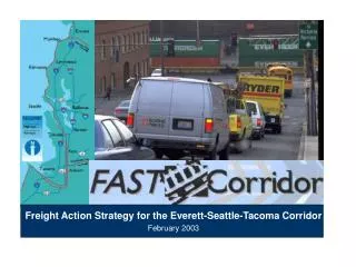
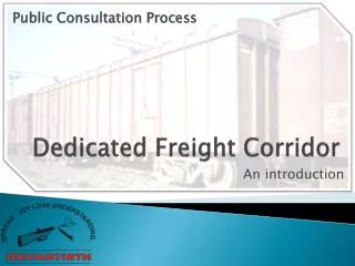
DFC Eastern and Western Dedicated Freight Corridor (DFC) Project is a mega rail transport capacity augmentation of Indian Railways (IR) Connecting the Eastern and Western parts of the country and the ports with the Northern hinterland Ludhiana – Dankuni EDFC Dadri – Mumbai WDFC 3338 km electrified
DFC DFCs would be different from typical dedicated Heavy Haul mineral lines between mining areas/industrial area to ports/consumption centres Traffic on DFCs would originate on Indian Railway feeder routes from the mining areas, ports and industrial areas and would be transferred to DFC at junction stations The destination of the trains would also be connected with DFC through feeder routes
DFC Axle load of 25 tonnes upgradable to 32.5 tonnes Ruling gradient of 1 in 200 (compensated) Maximum speed of 100 km/h Balancing speed of 65-75 km/h on up gradients 2X25 kV electrification system
The parameters of DFC for selecting type of locomotive are:Axle load – 25 t Speed – 100 km/hTrain load – 6000 t and 12000 t (coupled) BULK train on EDFC 4500 t DSC train on WDFCRuling gradient – 1:200 Requirements of DFC
Requirements of DFC • The locomotive should be able to • Start • And Achieve 65 to 75km/h Balancing speed • On • DFC with ruling gradient of 1:200 • Start • And Run through • On • Feeder routes with ruling gradient of 1:150 • A locomotive with 25 t axle load
REQUIRED STARTING CAPABILTIES 64.4 t 54.4 t
REQUIRED STARTING CAPABILTIES 49.9 t 42.1 t
Redundancy Concept in 9.0 MW Locomotive • Breakdown of drive side converter / traction motor: The power of the Locomotive shall be reduced only by 1/8th, only isolating the broken down equipment; • Breakdown of power unit during traction or electrical braking: The faulty power unit may be isolated; • Breakdown of an auxiliary converter: Redundancy in auxiliary converter shall be provided so that in the event of its failure, the traction capacity of the Locomotive does not get affected; • Breakdown in the air braking system of a bogie: It shall be possible to isolate the air brake in the bogie;
Redundancy Concept in 9.0 MW Locomotive • Breakdown in the electric control of the automatic air brake: It shall be substituted by the emergency brake; • Battery charger: The battery charger of each Bo-Bo unit shall be able to take care of battery charging needs of other Bo-Bo unit in case of failure of the battery charger; • Control electronics (VCU) shall have adequate redundancy so that a breakdown shall not affect the traction, braking and safety related control operations
Technical Requirements • Lubrication system for Gear/Pinion shall be kept separate from the TM bearings and Suspension tube bearings. • The loco shall be provided with GPS / GSM system through which fault details can be communicated to shed – Remote diagnostics
Technical Requirements • Air conditioned Cab • Context Sensitive Trouble Shooting Instructions on Driver Display • Wire less Synchronous Control – Two or more locomotives in a train (LOCOTROL)
Technical Requirements based on IR’s Experience of Locos - TEMPERATURE • It has been IR’s experience that the temperature inside the machine room near electronic cubicle of WAP5, WAG9 and WAP7 locos rises to more than 65deg Celsius during summer season when ambient temperature is as high as 47-48 deg Celsius. • This causes adverse affect on the cards in Indian conditions and high rate of failures of the cards is observed in WAP5/WAP7/WAG9 locos.
Technical Requirements based on IR’s Experience of Locos - TEMPERATURE • The cooling arrangement of the electronics shall be designed so that the temperature adjacent to the electronic cards remains below 45 ºC (degrees Celsius) while the Locomotive is operating OR • The cooling arrangement of the electronics shall be designed so that the temperature surrounding the cards shall be kept such that at least 20 deg C margin is maintained between Temp adjacent to card and Max temp allowed adjacent to card
Modes of Operation Other Features • Event Recorder • Voice recorder • FDU • Constant Speed mode • Inching Control mode • Shunting mode
CONCLUSION • The 7.0 MW and 9.0 MW, High Horse Power (HHP) locomotives • Would be a big leap forward in terms of locomotive technology on IR • The superior traction and braking capabilities, higher reliability, availability and energy efficiency of these locomotives would contribute significantly towards maximizing the transportation output on the DFCs and also on the Indian Railway feeder routes • During the process of induction of these modern high hp locomotives on the DFCs, there would be many important lessons learnt by IR in design, engineering, maintenance and operations of electric locomotives which would lead to further improvements in the future
TE Characteristics of 7.0 MW Locomotive with 40% starting adhesion
Power Vs Catenary Voltage Characteristics of 7.0 MW Locomotive
Propulsion Efficiency • The efficiency of propulsion system, consisting of • transformer, power converter and traction motor, of Locomotive • shall not be less than 87 % at full load • The efficiency of propulsion system shall be product of efficiency of transformer, power converter and traction motor, measured at full load • Efficiency at full load means, efficiency computed from parameters measured at conditions corresponding to full load and governed by IEC 60310 for transformer, IEC 61287 for power converter and IEC 60349-2 for traction motor
7.0 MW Locomotive with 35% starting adhesion
TE Characteristics of 9.0 MW Locomotive with 40% starting adhesion
9.0 MW Locomotive with 35% starting adhesion
Power Vs Catenary Voltage Characteristics of 9.0 MW Locomotive
Why Twin Bo-Bo ? • 6 axle locomotive having co-co configuration • can although deliver horse power in the range of 12000 • but can not deliver more than 60 t of starting TE due to limitation of adhesion • Leading locomotive manufacturers viz; M/s. Siemens, BT and Alstom have manufactured and delivered 12000 HP locomotive with TE in the required range with 8 axle twin Bo-Bo configuration • These type of locomotives are proven and design is readily available employing IGBT technology