Download
1 / 78
820 likes | 1.02k Views
Review of Computer Architetcure. A Sahu Deptt . of Comp. Sc. & Engg . IIT Guwahati. Outline. Computer organization Vs Architecture Processor architecture Pipeline architecture Data, resource and branch hazards Superscalar & VLIW architecture Memory hierarchy Reference.

E N D
Review of Computer Architetcure A Sahu Deptt. of Comp. Sc. & Engg. IIT Guwahati
Outline • Computer organization Vs Architecture • Processor architecture • Pipeline architecture • Data, resource and branch hazards • Superscalar & VLIW architecture • Memory hierarchy • Reference
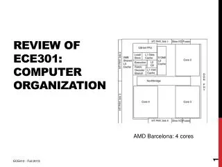
Computer organization Vs Architecture Comp Organization => Digital Logic Module Logic and Low level ============================ Comp Architecture = > ISA Design, MicroArch Design Algorithm for • Designing best micro architecture, • Pipeline model, • Branch prediction strategy, memory management • Etc…..
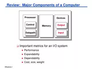
Hardware abstraction Register file ALU CPU PC System bus Memory bus Main memory Bus interface bridge I/O bus Expansion slots for other devices such as network adapters USB controller Graphics adapter Disk controller Mouse Keyboard Display Disk
Hardware/software interface C++ software m/c instr Arch. focus reg, adder • Instruction set architecture • Lowest level visible to a programmer • Micro architecture • Fills the gap between instructions and logic modules hardware transistors
Application Program Compiler OS ISA CPU Design Circuit Design Chip Layout Instruction Set Architecture • Assembly Language View • Processor state (RF, mem) • Instruction set and encoding • Layer of Abstraction • Above: how to program machine - HLL, OS • Below: what needs to be built - tricks to make it run fast
Programmer-Visible State PC Program Counter Register File heavily used data Condition Codes The Abstract Machine Memory CPU Addresses Code + Data PC ALU Registers Data Stack Instructions Condition Codes • Memory • Byte array • Code + data • stack
Instructions • Language of Machine • Easily interpreted • primitive compared to HLLs • Instruction set design goals • maximize performance, • minimize cost, • reduce design time
Instructions • All MIPS Instructions: 32 bit long, have 3 operands • Operand order is fixed (destination first) Example: C code: A = B + C MIPS code: add $s0, $s1, $s2 (associated with variables by compiler) • Registers numbers 0 .. 31, e.g., $t0=8,$t1=9,$s0=16,$s1=17 etc. • 000000 10001 10010 01000 00000 100000 op rsrtrd shamtfunct
Instructions LD/ST & Control • Load and store instructions • Example:C code: A[8] = h + A[8]; MIPS code: lw $t0, 32($s3)add $t0, $s2, $t0sw$t0, 32($s3) • Example: lw $t0, 32($s2) 35 18 9 32 op rsrt 16 bit number • Example:if (i != j) beq $s4, $s5, Lab1 h = i + j; add $s3, $s4, $s5else j Lab2 h = i - j; Lab1: sub $s3, $s4, $s5 Lab2: ...
What constitutes ISA? • Set of basic/primitive operations • Arithmetic, Logical, Relational, Branch/jump, Data movement • Storage structure – registers/memory • Register-less machine, ACC based machine, A few special purpose registers, Several Gen purpose registers, Large number of registers • How addresses are specified • Direct, Indirect, Base vs. Index, Auto incr and auto decr, Pre (post) incr/decr, Stack • How operand are specified • 3 address machine r1 = r2 + r3, 2 address machine r1 = r1 + r2 • 1 address machine Acc = Acc + x (Acc is implicit) • 0 address machine add values on (top of stack) • How instructions are encoded
RISC vs. CISC • RISC • Uniformity of instructions, • Simple set of operations and addressing modes, • Register based architecture with 3 address instructions • RISC: Virtually all new ISA since 1982 • ARM, MIPS, SPARC, HP’s PA-RISC, PowerPC, Alpha, CDC 6600 • CISC : Minimize code size, make assembly language easy VAX: instructions from 1 to 54 bytes long! Motorola 680x0, Intel 80x86
MIPS subset for implementation • Arithmetic - logic instructions • add, sub, and, or, slt • Memory reference instructions • lw, sw • Control flow instructions • beq, j Incremental changes in the design to include other instructions will be discussed later
D a t a R e g i s t e r # A d d r e s s P C I n s t r u c t i o n R e g i s t e r s A L U A d d r e s s R e g i s t e r # I n s t r u c t i o n D a t a m e m o r y m e m o r y R e g i s t e r # D a t a Design overview • Use the program counter (PC) to supply instruction address • Get the instruction from memory • Read registers • Use the instruction to decide exactly what to do
Division into data path and control DATA PATH control signals status signals CONTROLLER
Building block types Two types of functional units: • elements that operate on data values (combinational) • output is function of current input, no memory • Examples • gates: and, or, nand, nor, xor, inverter ,Multiplexer, decoder, adder, subtractor, comparator, ALU, array multipliers • elements that contain state (sequential) • output is function of current and previous inputs • state = memory • Examples: • flip-flops, counters, registers, register files, memories
Components for MIPS subset • Register, • Adder • ALU • Multiplexer • Register file • Program memory • Data memory • Bit manipulation components
PC 32 32 clock Components - register
PC PC+4 32 32 + + 4 offset 32 32 32 32 Components - adder
operation a=b overflow a ALU 32 result b 32 32 Components - ALU
PC+4 0 mux 1 32 32 PC+4+offset select 32 Components - multiplexers
5 R e a d r e g i s t e r 1 R e a d d a t a 1 5 R e g i s t e r R e a d r e g i s t e r 2 n u m b e r s R e g i s t e r s D a t a 5 W r i t e r e g i s t e r R e a d d a t a 2 W r i t e D a t a d a t a R e g W r i t e Components - register file
I n s t r u c t i o n a d d r e s s I n s t r u c t i o n I n s t r u c t i o n m e m o r y Components - program memory
M e m W r i t e R e a d A d d r e s s d a t a D a t a W r i t e m e m o r y d a t a M e m R e a d MIPS components - data memory
Components - bit manipulation circuits Sign xtend MSB 16 32 LSB shift MSB 32 32 0 LSB
MIPS subset for implementation • Arithmetic - logic instructions • add, sub, and, or, slt • Memory reference instructions • lw, sw • Control flow instructions • beq, j
Datapath for add,sub,and,or,slt • Fetch instruction • Address the register file • Pass operands to ALU actions • Pass result to register file required • Increment PC Format: add $t0, $s1, $s2 000000 10001 10010 01000 00000 100000 op rsrt rd shamtfunct
IM ad ins Fetching instruction PC
ins[25-21] rad1 RF rd1 ins[20-16] rad2 rd2 wad wd Addressing RF IM ad PC ins
ins[25-21] ins[20-16] ALU Passing operands to ALU rad1 RF IM rd1 ad PC rad2 ins rd2 wad wd
ins[15-11] Passing the result to RF ins[25-21] rad1 RF IM rd1 ins[20-16] ad PC ALU rad2 ins rd2 wad wd
+ 4 Incrementing PC ins[25-21] rad1 RF IM rd1 ins[20-16] ad PC rad2 ALU ins rd2 wad ins[15-11] wd
Load and Store instructions • format : I • Example: lw $t0, 32($s2) 35 18 9 32 op rsrt 16 bit number
DM rd ad 0 1 wd 16 sx ins[15-0] Adding “sw” instruction + 4 ins[25-21] rad1 RF IM rd1 ins[20-16] ad PC rad2 ALU ins rd2 wad ins[15-11] wd
0 1 1 0 Adding “lw” instruction + 4 ins[25-21] rad1 RF IM rd1 ins[20-16] ad PC rad2 DM ALU ins rd2 rd ad wad 0 1 ins[15-11] wd wd 16 sx ins[15-0]
0 1 + s2 Adding “beq” instruction + 4 ins[25-21] rad1 RF IM rd1 ins[20-16] ad PC rad2 DM ALU ins rd2 0 1 rd ad wad 0 1 1 0 ins[15-11] wd wd 16 sx ins[15-0]
28 ins[25-0] s2 0 1 ja[31-0] PC+4[31-28] Adding “j” instruction 0 1 + + s2 4 ins[25-21] rad1 RF IM rd1 ins[20-16] ad PC rad2 DM ALU ins rd2 0 1 rd ad wad 0 1 1 0 ins[15-11] wd wd 16 sx ins[15-0]
jmp Psrc RW MW Z M2R Asrc op 3 Rdst MR Control signals 28 ins[25-0] s2 0 1 ja[31-0] 0 1 PC+4[31-28] + + s2 4 ins[25-21] rad1 RF IM rd1 ins[20-16] ad PC rad2 DM ALU ins rd2 0 1 rd ad wad 0 1 1 0 ins[15-11] wd wd 16 sx ins[15-0]
brn ins[31-26] control Actrl ins[5-0] 2 opc Datapath + Control jmp 28 ins[25-0] s2 0 1 ja[31-0] 0 1 PC+4[31-28] + + Psrc s2 4 RW ins[25-21] rad1 MW RF IM Z rd1 ins[20-16] ad M2R PC rad2 DM ALU ins Asrc rd2 0 1 rd ad wad 0 1 1 0 ins[15-11] wd op 3 wd Rdst 16 sx ins[15-0] MR
Analyzing performance Component delays • Register 0 • Adder t+ • ALU tA • Multiplexer 0 • Register file tR • Program memory tI • Data memory tM • Bit manipulation components 0
+ 4 ins[25-21] rad1 RF IM rd1 ins[20-16] ad PC rad2 ALU ins rd2 wad ins[15-11] wd Delay for {add, sub, and, or, slt}
+ 4 ins[25-21] rad1 RF IM rd1 ins[20-16] ad PC rad2 DM ALU ins rd2 rd ad wad wd wd 16 sx ins[15-0] Delay for {sw}
tR R-class tR tM lw tR tM sw tR beq j Clock period in single cycle design clock period tI tA tR tI tR tA tA tI tI tA t+ t+ tI t+ t+ tI
Clock period in multi-cycle design clock period tI tR tA R-class tR tI tR tA tM tR lw tI tR tM tA sw tI tR tA beq t+ t+ tI t+ t+ j tI
Cycle time and CPI multi-cycle design high CPI pipelined design single cycle design low cycle time short long
PIpelineddatapath (abstract) IF ID EX Mem WB IF/ID ID/EX EX/Mem Mem/WB + 4 + rad RF IM rd1 ad PC DM ALU ins rd2 rd ad wad wd wd
Fetch new instruction every cycle IF ID EX Mem WB IF/ID ID/EX EX/Mem Mem/WB + 4 + rad RF IM rd1 ad PC DM ALU ins rd2 rd ad wad wd wd
Pipelined processor design IF/IDw flush 1 0 bubble control 0 1 0 + 4 + s2 rad1 RF IM rd1 rad2 ad PC DM ALU ins rd2 wad rd ad 0 1 1 0 wd wd PCw sx Actrl 0 1 PCw=0 IF/IDw=0 bubble=1
IM DM RF RF ALU Graphical representation 5 stage pipeline stages actions IF ID EX Mem WB
IM IM IM IM DM DM DM DM RF RF RF RF RF RF RF RF ALU ALU ALU ALU Usage of stages by instructions lw sw add beq