Download
1 / 40
400 likes | 578 Views
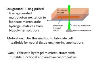
Pulsed laser deposited epitaxial garnet films for efficient low threshold waveguide lasers. Robert Eason , Tim May-Smith , Christos Grivas , Dave Shepherd , Optoelectronics Research Centre , University of Southampton, Highfield, SO17 1BJ, UK. E-mail: rwe@orc.soton.ac.uk. Contents.

E N D
Pulsed laser deposited epitaxial garnet films for efficient low threshold waveguide lasers Robert Eason, Tim May-Smith, Christos Grivas, Dave Shepherd, Optoelectronics Research Centre, University of Southampton, Highfield, SO17 1BJ, UK. E-mail: rwe@orc.soton.ac.uk
Contents • Pulsed laser deposition (PLD) • Motivations for thick (designer) films • Garnet crystals • Physical properties of films grown • Lasing from an unclad thick film • Self-imaging in a clad thick film • Conclusions
Pulsed laser deposition (PLD) 1 • The target material is ablated by a KrF excimer laser. • The ejected material forms a plasma plume and expands across to the substrate where it is deposited as a film. • The substrate is heated by a raster-scanned CO2 laser. • A background gas is used to control the plume stoichiometry and dynamics.
Pulsed laser deposition (PLD) 2 • The process of ablation preserves the stoichiometry of the target material well, meaning many different target materials can be used. Bulk off-cuts make very suitable targets. • Substrate heating allows epitaxial growth and hence films with high crystalline quality. CO2 laser heating can heat substrates to temperatures up to 2000 C. • The plume and film stoichiometry can be altered by a background gas. In the case of garnet crystal the use of oxygen is essential. • Relatively high growth rates up to 10 m per hourcan be achieved. • PLD is well suited to experimental work because it is relatively simple to change the setup and deposition conditions.
Important experimental parameters 3 • The target (crystal, sintered ceramic..) • The substrate temperature • Background gas used and pressure • Target-substrate distance • Energy density (laser fluence) on target • Repetition rate of the laser • Stability of all these with time (hours..)
Motivations for thick films 1 • Thick films reduce the effect of particulates. • Thick films have lower propagation losses than thin films. • Pump light can be coupled more easily into thicker films because there is a larger area to launch light into. • Cladding layers can be used to change the optical dynamics of thick waveguides and produce structures capable of self-imaging an input beam mode at the output face, or large-mode-area cladding-pumped devices for single-mode operation.
. n Thickness2 Length = n = refractive index, = wavelength Motivations for thick films 2 Self-imaging A single-mode laser beam focussed into the centre of a thick multi-mode waveguide will propagate multi-mode inside the guide and periodically self-image back to single-mode, obeying the formula: A Nd:GGG waveguide with an optimal length and thickness can be used as an amplifier that doesn’t change the mode of the signal beam. A device with a core thickness ~60 m could be efficiently pumped by diode bars.
Desired Structures: Designer films 3 • Thick multimode films Need film thicknesses of ≥ 50 mm to pump efficiently with high power diode laser arrays. • MultilayersCan be used for cladding pumping and to change the NA, making single-mode output possible.
Pump Laser light confinement Pump light confinement light Motivations for thick films 3 Cladding-pumping • Cladding layers increase the numerical aperture of a waveguide allowing more pump light to be launched. • Light guided by the cladding can pump the core as it passes through. • Index-matched cladding can be used to produce large-mode-area waveguides for high power single-mode operation.
Versatile Garnet Crystals 1 • Excellent laser host • Optically isotropic • Wide transparency range • High mechanical strength • Good thermal conductivity • Easy to growHigh quality films can be grown by PLD. • Many different garnetsDifferent refractive indices but similar thermal expansions and lattice sizes. • Useful material systemIdeal for multilayer structures. We have grown all of the garnets highlighted in blue
25000 Nd:GGG (400) Nd:GGG (800) Intensity (counts) YAG (800) YAG (400) 0 10 20 30 40 50 60 70 80 2q (degrees) Nd:GGG General Properties • ‘Water clear’The first test of quality is if films look clear to the naked eye. • Highly textured crystalXRD peaks approaching bulk quality. • Gallium deficientGallium is preferentially lost in the deposition process. • Broadened SpectroscopyDue to the slightly deficient stoichiometry and crystal structure. EDX & RBS Gd:Ga – 3:4 O – 60%
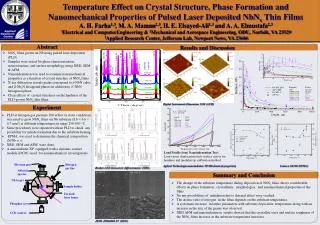
Physical properties of films grown 1 • Nd:GGG films with thickness up to 135 m have been grown on YAG (100) substrates, the thickest reported to date by PLD. • X-ray diffraction shows that the films are epitaxial and of high crystalline quality. • Rutherford back scattering analysis shows that the films have a stoichiometry close to that of the bulk material.
Physical properties of films grown 2 • The films have fluorescence and absorption properties close to that of bulk, but slightly broadened.
2 experiments using different substrate-target distances suggest a pressure of about 5 ×10⁻² mbar minimises the gallium deficiency. Unstable pressure leads to poor films because the composition varies throughout depth. Composition vs. O2 pressure 3 target-substrate distance = 4 cm extrapolated minimum ~ 4.6 ×10⁻² mbar target-substrate distance = 6 cm minimum ~ 4.7 ×10⁻² mbar
XRD and EDX can be used to analyse crystal structure and composition respectively. Lattice increases as gallium deficiency gets worse. Composition vs. Lattice 4 Gadolinium ions are occupying gallium lattice sites, making the lattice bigger and producing strain in the film. Ionic radii for the octahedral site: Thick films cannot tolerate the strain produced, and are liable to crack when polishing.
Where is the gallium going? 5 • Pattern for vertical and horizontal spread • Rectangular spot! – Aspect ratio of spot is important. vertical spread horizontal spread
The ideal substrate temperature is about 800 °C. The composition only starts to be affected when the substrate temperature is too high. Substrate temperature is actually more critical to the crystal structure. 4.10 3.90 3.70 8-x Ga x 3.50 X in Gd Intensity (arb. units) Intensity (arb. units) 3.30 Intensity (arb. units) 3.10 2.90 650 750 850 950 1050 Temperature (°C) [estimate] Composition vs. Substrate Temperature 6 2q (degrees) 2q (degrees) 2q (degrees)
Composition vs. substrate-target distance 7 • This trend of recovering gallium inclusion suggests that gallium can’t simply be diverging faster than gadolinium in the plume. • Perhaps gallium is re-sputtered out of the film if it is too close to the target.
Composition vs. fluence(constant spot size) 8 • Range of acceptable fluences. • Spot aspect ratio is perhaps more important.
Problem 1 - Particulates • Particulates can form scattering centres and contribute significantly to the overall loss. • Solutions: • Burial • Thick films are less affected. • Capping layers allow burial without increasing the core size. • Target reconditioningRestricting growth runs to < 2 hours prevents the target surface degrading by a significant amount.
Problems 2 – Film Stress • Gallium deficiency in GGG films causes film stress which can lead to cracking. • Varying growth conditions (in particular oxygen pressure) produces different compositions. • EDX and XRD used to determine compositions and lattice constants respectively. • End view of cracked waveguide Solution: • Precise stoichiometry control Optimise growth conditions to minimise the gallium deficiency.
Lasing from an unclad thick film 1Ti:sapphire pumping • Lasing has been achieved in a 40 m thick unclad Nd:GGG film. • An absorbed pump power threshold of 18 mW was observed using a high-reflectivity output coupling mirror. • Lasing has been observed at 1060.6 nm and at both 1059.0 and 1060.6 nm for pump powers approximately twice that of threshold. • Slope efficiencies of 17.5% and 12.3% have been obtained using two output coupling mirrors with different reflectivities.
Ti:sapphire Pumped Nd:GGG • 17.8 mWLowest threshold with a 40 μm thick film. • 32.0%Highest slope efficiency with a 50 μm thick film. • 0.1 dBcm-1Lowest loss with a 40 μm thick film.
Tim? How do the last two slides compare. The slope efficiencies quoted are different. • I’d like to show the ‘best’ slope efficiency onlt etc..
Lasing from an unclad thick film 2Ti:sapphire pumping • The threshold for lasing using output couplers with different reflectivity’s can be used to estimate propagation losses using the Findlay-Clay technique. • An estimate of 0.1 dBcm-1 has been obtained for the propagation loss, the lowest reported to date for a PLD grown waveguide. • This result emphasises the advantage of thicker films, and should be improved upon with the inclusion of capping layers. R = output coupler reflectivity, L = cavity length.
Insert here the two figs side by side from your thesis (5.3.5 and 5.3.6)
Self-imaging in a clad thick film 1 • Self-imaging of a single-mode Ti:sapphire laser beam has been observed in a 25-35 m thick (uneven) Nd:GGG film grown on a YAG (100) substrate with a 10 m YAG capping layer. • The modal output changed as the wavelength of the Ti:sapphire laser was tuned, and as the launch position was changed to different thicknesses of the sample.
Guided direction Unguided direction Self-imaging in a clad thick film 2 • For a setup with the wrong thickness and wavelength for self-imaging, the output was multi-mode.
Guided direction Unguided direction Self-imaging in a clad thick film 3 • For a setup obeying the self-imaging formula, a single-mode beam with a 6 m diameter spot at the input face was reproduced at the output face.
Diode-Pumping Launch Setup 1 Beam shaping Output coupling mirror HR @ 808 nm 12.86%T @1064 nm Input coupling mirror HT @ 808 nm HR @1064 nm Waveguide coupling final cylindrical lens • Side-pumping not yet possible due to difficulties produced by film stress (as mentioned earlier). Side-pumping is preferable because it is more practical and scalable (make device longer and use more diodes). • Launch efficiency ~80% for a 50 mm thick waveguide. • Incident power limited to 100 W by mirror contact fluid boiling. Laser output 50 mm thick Nd:GGG waveguide on a YAG substrate Fabricated using three deposition runs and polished back to make a slab waveguide 3-bar diode stack Each bar = 60 W max @808 nm Doublet lens Cavity mirrors Primary cylindrical lens
Diode-Pumping Results 2 • The device operated with unstable highly multimode output. Solution: • Multilayers and cladding pumping.
Diode-Pumping Results 3 • 7.44 W Threshold with a 2.00%T mirror. • 11.2% Slope efficiency with a 12.86%T mirror. This could be improved better spatial overlap of pump and signal. • 4.0 W Highest output for a film grown by PLD. Potential for more with a better film. • 0.8 dBcm-1Loss from the Findlay-Clay technique (uses thresholds from different output couplers to deduce loss).
Multilayer Trial Fabrication 1 • SEM imaging further confirms the existence of the multilayers. • A large index difference is required for the pump cladding to substrate and superstrate steps. A small index difference is required for the core to pump cladding steps. Cladding pumping illustration Single-mode laser output Multimode pump propagation
Multilayer Trial Fabrication 2 • A trial multilayer structure was fabricated by sequential deposition of YGG, Nd:GSGG, YGG and YAG. • Layers were kept thin to allow them to all be detected by XRD. • An EDX linescan across the layers shows their different compositions.
YbAG Thin-Disk Laser Attempt • Crystallinity and stoichiometry close to bulkBest film overall in terms of XRD and EDX. • Absorption not the same as bulkWe suspect that some of the ytterbium is in the 2+ valence state.
Growth of Alternative Garnets • 7 different garnets depositedEpitaxial growth of highly textured YAG, YGG, YSAG, GGG, GSAG, GSGG & YbAG. • Best XRD: YSAGClosest match to the YAG substrates. • Best EDX: GSAGElements found to be least susceptible to loss in the deposition process. • Quaternary garnets better than tertiary garnetsScandium retained more easily than gallium and aluminium. • Scene is set for multilayer garnet crystal films
Summary 1 • The fabrication and processing techniques have been proven successful for these two basic first steps towards more advanced structures. • Stoichiometry control needs to be improved to avoid cracking problems due to film stress. • With a carefully chosen optics setup, high power levels from diode stacks can be coupled efficiently into PLD waveguides. • Improved loss, output power and slope efficiency should come with improved crystal quality. • PLD films can tolerate a high level of pumping power without cracking.
Ideas for the future 1 • Graded index • Graded dopant concentration • Blended layers • Hybrid garnets • Cross-beam……
Ideas for the future 2 • Tim. Simple 3 quad laser cross beam pic?