Download
1 / 50
810 likes | 1.53k Views
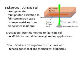
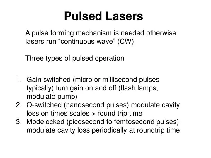
Pulsed Lasers. A pulse forming mechanism is needed otherwise lasers run “continuous wave” (CW) Three types of pulsed operation. Gain switched (micro or millisecond pulses typically) turn gain on and off (flash lamps, modulate pump)

E N D
Pulsed Lasers A pulse forming mechanism is needed otherwise lasers run “continuous wave” (CW) Three types of pulsed operation • Gain switched (micro or millisecond pulses typically) turn gain on and off (flash lamps, modulate pump) • Q-switched (nanosecond pulses) modulate cavity loss on times scales > round trip time • Modelocked (picosecond to femtosecond pulses) modulate cavity loss periodically at roundtrip time
Gain Gain region No absorption Below energy gap Loss region 0 Log(Iout/Iin) Absorption The “Mode” in “Mode-locking” is longitude Models Many longitudal modes can co-exists in the same cavity
Mode-Lock The relative phases of the simultaneously lasing cavity modes must be “locked” at proper values. Roughly:
How to achieve Mode-lock Laser with many modes but without mode-locking
Relative phases of the modes are random • Output looks completely random but repeats itself in time equal to 2L/c • Slow photodetectors see only the average power Q: which of the above are still true under mode-lock condition?
How to achieve Mode-lock Design a cavity so that the round-trip loss of the light is BIG, unless the modes are “lock” to generate short pulses. Two Types of techniques: • Saturated absorbers due to limited number of absorbing particles (e.g., dye molecules) • Nonlinear effect: Kerr lens
Optical Kerr Effect • A change in the refractive index of a material in response to an electric field. • The change is proportional to the square of the electric field • All materials show Kerr effect • Optical Kerr Effect is the special case where the electric field is from the light itself
Kerr Lens Mode-locking • Kerr Lens & Aperture gives increased transmission at high Intensity • Increased transmission at high intensity • Short, intense pulse preferred in laser • Kerr effect instantaneous
Dispersion in Optics The dependence of the refractive index on wavelength has two effects on a pulse, one in space and the other in time. Dispersion disperses a pulse in space (angle): “Angular dispersion” dn/dl Dispersion also disperses a pulse in time: “Chirp” d2n/dl2 Both of these effects play major roles in ultrafast optics.
In most of the region, n increases as frequency of the light increase angular frequency.
Group Velocity: The velocity with which the envelope of the wave propagate through space. • : angular frequency. k: angularwave number k = 2 / • is the same in or out of the medium; • but k = k0n, where k0 is k in vacuum, and n is what depends on the medium.
A Simple Derivation of Group Velocity: v = /k
Group Velocity in terms of Optical dispersion Vphase = c0 / n Conclusion: group velocity has nothing to do with the true velocity of the light
The group velocity is less than the phase velocity in non-absorbing regions. • vg = c0 / (n + wdn/dw) • Except in regions of anomalous dispersion (which are absorbing), dn/dw is negative, that is, near a resonance. So vg > vphase for these frequencies!
Group Velocity vs. Wavelength We more often think of the refractive index in terms of wavelength, so let's write the group velocity in terms of the vacuum wavelength l0. Consider the simplest case: dn/d0 = = constant This means vg is independent of wavelength
The effect of group velocity dispersion • GVD means that the group velocity will be different for different wavelengths in the pulse. early times late times vgr(yellow) < vgr(red) is the “group velocity dispersion.”
Calculation of the GVD (in terms of wavelength) Recall that: and Okay, the GVD is: Units: s2/m or (s/m)/Hz or s/Hz/m Simplifying:
GVD yields group delay dispersion (GDD). We can define delays in terms of the velocities and the medium length L. The phase delay: so: The group delay: so: GDD = GVD L The group delay dispersion (GDD): so: Units: fs2 or fs/Hz
Manipulating the phase of light Recall that we expand the spectral phase of the pulse in a Taylor Series: and we do the same for the spectral phase of the optical medium, H: phase delay group delay group delay dispersion (GDD) So, to manipulate light, we must add or subtract spectral-phase terms. For example, to eliminate the linear chirp (second-order spectral phase), we must design an optical device whose second-order spectral phase cancels that of the pulse: i.e.,
So how can we generate negative GDD? This is a big issue because pulses spread further and further as they propagate through materials. We need a way of generating negative GDD to compensate.
Suppose that some optical element introduces angular dispersion. Angular dispersion yields negative GDD. Optical element If frequency w0 propagates a distance L to plane S’, j then frequency w sees a phase delay of j(w) w Input beam L P0 w The GDD due to angular dispersion is always negative!
w w Lsep How can we use dispersion to introduce negative chirp conveniently? A prism pair has negative GDD Assume Brewster angle incidence and exit angles. Always positive (in visible and near-IR) Always negative! This term assumes that the beam grazes the tip of each prism This term allows the beam to pass through an additional length, Lpriam, of prism material. Vary the second term to tune the GDD!
Adjusting the GDD maintains alignment. Any prism in the compressor can be translated perpendicular to the beam path to add glass and reduce the magnitude of negative GDD. Remarkably, this does not misalign the beam. New prism position Original path through prism New beam path through prism Original and new path out of the prism Original prism position
Pulse Compressor This device has negative group-delay dispersion and hence can compensate for propagation through materials (i.e., for positive chirp). The longer wavelengths have a longer path. It’s routine to stretch and then compress ultrashort pulses by factors of >1000
Ti:Sapphire laser • Optically active atoms TiO3 <1% by Weight • Host solid is sapphire (Al2O3) • Ti interacts with solid so the E2, E1 broadened significantly (inhomogeneous broadening). The atoms in the solid vibrate and interact with the Ti atoms. • Gain bandwidth huge (100 THz) • Can use as tunable laser • Makes for ultra short pulses
Titanium Sapphire Ti3+: Al2O3 E 3/2 excited state 2T2 ground state Spin forbidden: long emission lifetime 300 ms Reasonable extinction coefficient e=14000 Huge Stokes shift, Broad emission spectrum compared to dyes Revolutionized laser industry in ability to make tunable short pulses
Tuning Range and Power of Ti:Sapphire Longer wavelengths Less damaging 900 is often good Compromise between Power and viability 100 femtosecond pulses 10 nm FWHM bandwidth Excite essentially every dye With this wavelength range
end Output coupler • Pumped by Argon ion or doubled Nd laser • Birefringence filter used for color tuning
Introduction to Non-linear Optical effects • NLO effects have been observed since 19thC • Pockels effect • Kerr effect • High fields associated with laser became available in the 1960s and gave rise to many new NLO effects • second harmonic generation (SHG) • third harmonic generation (THG) • stimulated Raman scattering • self-focussing • In NLO we are concerned with the effects that the light itself induces as it propagates through the medium • In linear optics the light is deflected or delayed but its frequency (wavelength) is unchanged
Pulse Compression Simulation Resulting intensity vs. time with only a grating compressor: Note the cubic spectral phase! Using prism and grating pulse compressors vs. only a grating compressor Resulting intensity vs. time with a grating compressor and a prism compressor: Brito Cruz, et al., Opt. Lett., 13, 123 (1988).
Pulse compressors achieve amazing results, but, if not aligned well, they can introduce spatio-temporal distortions, such as “spatial chirp.” • Propagation through a prism pair produces a beam with no angular dispersion, but the color varies spatially across the beam. • Care must be taken to cancel out this effect with the 3rd and 4th prisms. Prism pairs are inside nearly every ultrafast laser, so we’re just asking for spatial chirp. Color varies across beam
Spatial chirp is difficult to avoid. • Simply propagating through a tilted window causes spatial chirp! Different colors have different refractive indices and so have different refraction angles. Color varies across beam n(w) Because ultrashort pulses are so broadband, this distortion is very noticeable—and problematic!
Angular dispersion also causes pulse fronts to tilt. Phase fronts are perpendicular to the direction of propagation. Because group velocity is usually less than phase velocity, pulse fronts tilt when light traverses a prism. Pulse-front tilt and angular dispersion are manifestations of the same effect and their magnitudes are directly proportional to each other.
Angular dispersion causes pulse-front tilt even when group velocity is not involved. Diffraction gratings also yield a pulse-front tilt. The path is simply shorter for rays that impinge on the near side of the grating. Of course, there’s angular dispersion, too. Since gratings have about ten times the dispersion of prisms, they yield about ten times the tilt.
Chirped mirror coatings offer an alternative to prisms and gratings for dispersion compensation. Longest wavelengths penetrate furthest. Such mirrors avoid spatio-temporal effects, but they have limited GDD. Doesn’t work for < 600 nm
Different prism materials The required separation between prisms in a pulse compressor can be large. The resulting negative GDD is proportional to the prism separation and the square of the dispersion. Compression of a 1-ps, 600-nm pulse with 10 nm of bandwidth (to about 50 fs). Kafka and Baer, Opt. Lett., 12, 401 (1987) It’s best to use highly dispersive glass, like SF10, or gratings.
Diffraction-grating pulse compressor The grating pulse compressor also has negative second-order phase. Grating #2 w w where d = grating spacing (same for both gratings) Lsep Note that, as in the prism pulse compressor, the larger Lsep, the larger the negative GDD. Grating #1
Compensating 2nd and 3rd-order spectral phase Use both a prism and a grating compressor. Since they have 3rd-order terms with opposite signs, they can be used to achieve almost arbitrary amounts of both second- and third-order phase. Prism compressor Grating compressor Given the 2nd- and 3rd-order phases of the input pulse, jinput2 and jinput3, solve simultaneous equations: This design was used by Fork and Shank at Bell Labs in the mid 1980’s to achieve a 6-fs pulse, a record that stood for over a decade.
H(w) Optical device or medium Spectral Phase and Optical Devices We simply add spectral phases. jH(w) = 2L / = k(w) L The phase due to a medium is:k(w) L = k0 n(w) L To account for dispersion, expand k(w) = k(w0) + 1[w-w0] + 1/2 2[w-w0]2
The Group-Velocity Dispersion (GVD) The first few terms are all related to important quantities. The third one is new: the variation in group velocity with frequency: is the “group velocity dispersion.”