Download
1 / 19
190 likes | 322 Views
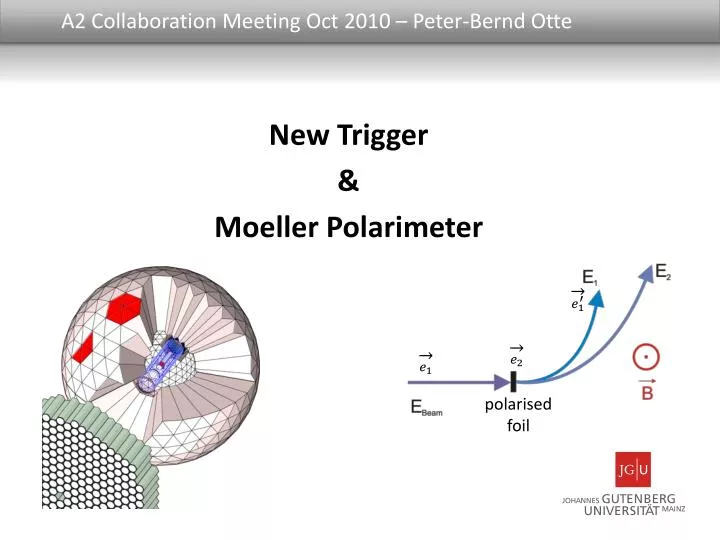
A2 Collaboration Meeting Oct 2010 – Peter-Bernd Otte. New Trigger & Moeller Polarimeter. polarised foil. Brevity is the soul of wit. FPGA. = semiconductor chip FPGA = many electronics modules (OR, MLU, timer) cables n o CPU!. ~3 cm. ~ meters. Part A: New Experiment Trigger.

E N D
A2 Collaboration Meeting Oct 2010 – Peter-Bernd Otte New Trigger & Moeller Polarimeter polarised foil
Brevity is the soul of wit FPGA = semiconductor chip • FPGA = • many electronics modules (OR, MLU, timer) • cables • no CPU! ~3 cm ~ meters
Part A: New Experiment Trigger “VUPROM” from GSI with “Virtex 4” from XILINX Setup of New Trigger CB(NaI) level converter & cable cables masterVUPROM 1st stage VUPROM Exp. trigger discriminator output 1st stage VUPROM clustering & logic PID 1st stage VUPROM 1st stage VUPROM 70ns 20ns 15ns
Part A: New Experiment Trigger Trigger = 2 hits in plane with incoming g (only azimuthal) |f1 – f2| = 180 deg divide CB into 48 azimuthal bins “hardwired” trigger with ANDs and ORs immediate trigger result Livetime = ~100% rate: 580Hz (while M1+ = 16k, M2+ = 3.6k) Coplanarity trigger 24x sublogic AND OR direction of beam Simulation by Cristina Collicott (D. Hornidge)
Part A: New Experiment Trigger Measured: Azimuth angle difference between hit channels in CB Coplanaritytrigger Number of clusters (M) determined by FPGA logic
Part A: New Experiment Trigger Setup of New Trigger: Multiplicity Trigger Detailed hit pattern needed full readout! signal to all: Send full hit pattern CB(NaI) level converter & cable cables masterVUPROM 1st stage VUPROM Exp. trigger 1st stage VUPROM PID 1st stage VUPROM 70ns 20ns 15ns 1st stage VUPROM + 100-120ns 310ns
Part A: New Experiment Trigger cellular logic Steps • gather hit pattern (330ns) • Shrink clusters (60ns)(using set of rules)until no more changes • Count number of cells(20ns)= number of clusters • If desired cluster count trigger! Multiplicity cluster algorithm crystal scheme of CB
Rates: livetime: 98.7% Next step: determine purity and efficiency Same trigger algorithms can be extended to cover also TAPS Multiplicity Trigger: Rates
Part B: Moeller Polarimeter Use Moeller scattering • measure 2 coincident electrons DAQ necessary • Count asymmetry beam polarity Introduction electron beam polarimetry use Tagger polarised foil
Part B: Moeller Polarimeter Moeller radiator Tagger 4x VUPROMs Moeller Polarimeter Setup VUPROM 1 AB UV VUPROM 2 EF ST VUPROM 3 GH QR VUPROM 4 IJ OP Complete DAQ on a chip.Per FPGA:24x TDC (resolution 50ps) & 50 histograms 1 352 Detectors of Tagger
Part B: Moeller Polarimeter Moeller electronics and DAQ work! Raw data: Electronics and DAQ 1 352
Part B: Moeller Polarimeter Count asymmetries okay! Abs. value not okay, due to problematic energy calibration of Tagger Results: MAMI angle scan 450MeV beam energy 1557MeV beam energy
Part B: Moeller Polarimeter Moeller electronics and DAQ work! Raw data: Electronics and DAQ Why important? 1 352 Expected Moeller pairs.But energy shift measured: 4 to 12 channels
Part B: Moeller Polarimeter Why? • e- entry angle Moeller >> bremsstrahlungTagger calibration only valid for small angles Result: Mapping of electron energy and angle dependent. shift in measured energy Origin of measured energy shift (Tagger optics) neg. angle e- pos. angle
Part B: Moeller Polarimeter same e- energy and entry anglebutdifferent angles signs Simulate Moeller electrons (Tagger optics) energy shift in MeV Taggerchan. (450 MeV beam energy)
Part B: Moeller Polarimeter Sum of energy shift Simulate Moeller electrons (Tagger optics) measurement
New coplanarity & multiplicity trigger: works! • Remaining: purity, efficiency? next weeks Moeller polarimeter • count rate asymmetries: okay • abs. polarisation: unknown ideas welcome has this been discovered in the past? Summary
Part B: Moeller Polarimeter Ingredients: • simulated field map (MAMI B or MAMI C?) • map electrons (0..450MeV) onto tagger ladder/beam dump Setup of Simulation (Tagger optics) Beam dump tagger ladder Esimulation / Ecalibration e- gun Tagger channel Use own calibration for calculations Ian Antonow
Part B: Moeller Polarimeter scattering angle: 94-92% loss of Moeller e- due to small Tagger pol shoe gap Simulate Moeller electrons angle in lab frame Moeller e-180MeV 1508MeV • Simulation only in accelerator plane bremsstrahlung e- pole shoes Moeller e-