Download

1 / 21
210 likes | 332 Views
Velocity Reconstruction from 3D Post-Stack Data in Frequency Domain. Enrico Pieroni , Domenico Lahaye, Ernesto Bonomi Imaging & Numerical Geophysics area CRS4, Italy. Non-linear inversion of post stack data for velocity analysis.

E N D
Velocity Reconstruction from 3D Post-Stack Data in Frequency Domain Enrico Pieroni, Domenico Lahaye, Ernesto Bonomi Imaging & Numerical Geophysics area CRS4, Italy
Non-linear inversion of post stack data for velocity analysis • Subsoil imaging by inverting Zero-Offset seismic data in space-frequency domain • Optimal control of the error norm between real and • simulated data • direct problem: modeling by demigration • adjoint problem: error residual migration • minimization: line search along the error gradient in the velocity space • A sequence of nested non-linear inversions, from the • lowest to the highest frequency • Algorithm embarassingly parallel in frequencies
S G1 G2 1 way, v/2 2 way travel path vith vel. v What are post-stack data? Offset acquisition: Hundreds of shots & Thousands of receivers Stacking = compression of data to virtually zero-offset traces (S=G). Model: exploding reflectors with halved velocities
Direct Problem in the w Domain • Demigration mapping: q(n) P(0) • final value problem in which the zero offset data are modeled from medium reflectivity • P(n) = acoustic wave field at depth z(n) = (n-1)Dz • D(n) = upward propagator • v(n)(x) = v(x, y, z(n)) = velocity field • q(n) = normal-incidence reflectivity • Eqns decoupled in frequencies: embarassing data parallelism
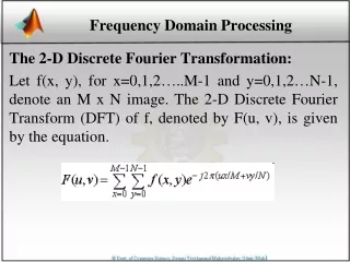
Upward propagator Scalar wave equation UPWARD + DOWNWARD separation Upward propagate data from reflectors to surface with halved velocity: one way wave equation Laterally invariant velocities: & FFT = Fourier matrix (x,y) -> (kx,ky) & for laterally variable velocities: V(n) = medium velocity at depth n correction PS exact vel. normal prop.
Build reflectivity from v • Due to orthogonal incidence: • velocity isosurfaces reflectors • gradient filtering • Edge detection for IP
Minimization Problem: Optimal Control Approach • S= Z.O. “known” data • P(0) = Z.O. simulated data ( = field P @ surface) • Find velocity v minimizing the misfit function j • Constrained minimization: Lagrange multipliers method
Adjoint Problem in the w Domain • l(n) = adjoint wave field at depth z(n) = (n-1)Dz • D = adjoint operator, ~ downward propagator D* • dL/dP(n) = 0 • Migration mapping: initial value problem (if misfit = 0 then l =0)
Building the gradient • Constraining l(n) and P(n) to satisfy the direct and the adjoint equation: • & from the first variation of the Lagrange function: • = adjoint downward propagated Diff[D] direct upward prop. field • = 0 if l=0
Optimization strategy • Number of parameters p = NxNyNz ~ 108 huge search space: no Hessian or Montecarlo work lot of local minima Hessian evaluation requires running p direct problems • Conjugate gradientto reduce computation, storage and search time • - Gradient evaluated by automatic differentiation • - CG + orthogonal projection Vmin .LE. v(x,y,z) .LE. Vmax • - conjugate directions build with Fletcher-Reeves updating • Line search by Golden bracket + Polynomial- search interval bounded when the at least 1 velocity component reach the bound • Inversion adaptive in time-frequency to stabilize solution
v z 1D Test cases • 1D is fully analytical both in the discrete and in the continuum • “scissors” ambiguity: • v(z)v’(z) = a v(z/a) • Good 1st guess + adaptive in freq.
+ 4 ord. mag. [0,12.5 Hz] 200 itns [0,25 Hz] 200 itns Step exact vel constant initial guess 5 ord. mag. Test 1: discontinuous velocitynf=100 fmx=50 Hz
+ 3 ord. mag. [0,37.5 Hz] [0,50 Hz] + 5 ord. mag. Test 1
[0,12.5 Hz] Parabolic exact final 3 orders of magnitude linear 1st guess [0,25 Hz] final + 5 orders of magnitude 50 itns showed every 10 Test 2: continuous velocitynf=100 fmx=50 Hz
Handmade 1st guess model, based on previous& 50 itns with all w assessing first 10 layers [0,25 Hz] 100 itns [0,12.5 Hz] 100 itns Linear 1st guess Test 3: disc. velocity + inversionnf=100 fmx=50 Hz exact
Test 3 [0,50 Hz] 200 itns [0,37.5 Hz] 100 itns
Conclusion & Further Developments • Control of the error to decide how to proceed, to be done automatically • Velocity estimate from the lowest to the highest frequency (other: sliding windows, back & forth, …) , to be done automatically • Dev: 3D feasible thanks to parallelization in frequencies (3D should also remove a lot of ambiguities) • Perspective: integrate with a multi-scale spatial approach from the lowest to the highest depth • Dev: correct ZO for geometrical spreading & amplitude • Open problem: optimal tuning of the reflectivity for real data
Pragmatic inversion: Migration & Downward propagate data at surface with halved velocity; & One way wave equation: for laterally invariant velocities & FFT = Fourier matrix (x,y) -> (kx,ky) & for laterally variable velocities vj(n) = reference velocities F = shape functions
Goal: subsoil imaging from post-stack data in frequency domain determing the velocity model of the subsoil in such a way that the simulated (modeled) and measured (given) pressure field at the surface(stacked sections) agree simulation code: - in frequency domain: * data compression and hence reduced computational cost * typical problem dimension: 500 MB - 1 GB * direct/adjoint propagation of data by phase shifting - in 3D - highly innovative approach - weak points: * reflectivity (isosurfaces of velocity discontinuities) * amplitude mathematical model: Lagrangian formulation - cost function: difference between simulated and measured stacks - constraints: one-way wave equation (in frequency domain) - direct field: demigration (upward) from reflectivity to recorded data - adjoint field: migration (downward) driven by source term (residual error) fromsurface data to adjoint field - migration operatorand derivative - gradient: Integral of (direct field * OP * adjoint field) dx dy dz dw - weak points: computation of OP and gradient algorithm: projected CG (PCG) optimization for the velocity model updating implementation: Fortran90 + MPI