Download
1 / 17
170 likes | 174 Views
Upgrade of the TileCAL LVPS System. Gary Drake Argonne National Laboratory, USA In Collaboration with The University of Chicago. ATLAS Upgrade Workshop. CERN Feb. 25, 2009. Outline of Talk. Goals for the LVPS Upgrade Current Plans & Thinking

E N D
Upgrade of the TileCAL LVPS System Gary Drake Argonne National Laboratory, USA In Collaboration with The University of Chicago ATLAS Upgrade Workshop CERN Feb. 25, 2009
Outline of Talk • Goals for the LVPS Upgrade • Current Plans & Thinking • Primary Issues, Critical Decisions, Required R&D • Summary
General System Guidelines and Goals for the LVPS System • Primary Motivation: Improve radiation hardness of electronics • LVPS bricks must be replaced for sLHC environment… • Improve Reliability • Connectors • Reduce number of connections & interconnects • Improve reliability and robustness of connectors • Implement redundancy to prevent single-point failures • Generally reduce complexity of system where possible • Reduce numbers of voltages to be generated • Eliminate sensitivities to IR drops • Eliminate need for tight regulation by LVPS • Use “point-of-load” regulators CERN rad-hard regulators
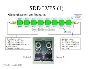
The Current LVPS System +3DIG, +5DIG, -5MB, +5MB, +15MB, -15HV, +15HV, +5HV And Returns • Present System Architecture – 2-Stage System FE Circuitry In Drawer On Detector 1 per Drawer On Detector 1 per 4 Drawers USA15 Mother Boards 200VDC Local CKTs LVPS 200VDC 14 Splitter Box To Other Drawers Digitizers Local CKTs Bulk 200 VDC 4 Stage 2 Digitizers To Other Splitter Boxes Local CKTs 4 HV Dist. System Stage 1 Local CKTs 6
splitter box splitter box splitter box The Current LVPS System USA15 • TileCAL LVPS System – 2-stage system 200 V dc 3 f 240 VAC 200 V dc BULK SUPPLY 200 V dc CustomLVPS BoxesOne per Drawer256 Total Commercial24 HPS1 UnitsEach powers 12 fLVPS Main Barrel side70m long cable Extended Barrel sides100m long cable 200 V dc in,3V, 5V, 15V Out Graphic by I. Hruska, B. Palan
The Current LVPS System • Current fLVPS configuration Power Daisy Chain HV Capton Foil HV control and distribution board HV control and distribution board 6 Harting connector pmt 3in1 pmt 3in1 Power daisy chain 6 12 8 LVPS Motherboard Motherboard Motherboard Motherboard 14 4 4 4 4 4 4 4 4 Digitizer Digitizer Digitizer Digitizer Digitizer Digitizer Digitizer Digitizer 100 100 TTC optical Interface Flex Foils (data,TTC ) BUS data to ROD Graphic by G. Usai, UC
The Current LVPS System • Current Configuration of LVPS Box 72 pin Harting Connector LVPS Box 8 Bricks/Box 200V Dist. Board 200 VDC 6 +3DIG & Returns +3DIG Brick 4 +5DIG & Returns +5DIG Brick 4 Ground +5MB & Returns +5MB Brick 8 6 -5MB & Returns -5MB Brick 4 +15MB & Returns +15MB Brick 2 +5HV & Returns +5HV Brick ELMB Mother Board CAN Bus 2 -15HV & Returns 10 -15HV Brick 2 +15HV & Returns +15HV Brick 2 Range of Voltages: 5:1 Range of Currents: 62:1 • One Basic Brick Design Different Component Values
The Proposed New Power Distribution System FE Circuitry In Drawer On Detector 1 per Drawer On Detector 1 per 4 Drawers +/-10VDC and Returns • New System Architecture – 3-Stage System USA15 200VDC POL REGs Local CKTs LVPS 200VDC 4 (8*) Splitter Box To Other Drawers Bulk 200 VDC Stage 2 To Other Splitter Boxes POL REGs Local CKTs 4 (8*) Stage 1 POL REGs Local CKTs 4 (8*) Stage 3 - Point-of-Load Regulators * Numbers in parentheses for implementation of redundancy
Point of Load Regulators +/-10VDC POL REGs Local CKTs • Contact persons: F. Faccio & G. Blanchot • More info http://indico.cern.ch/conferenceDisplay.py?confId=39721 • We will be testing prototypes as soon as they become available • Caveat: Not working on rad-hard negative voltage regulators (yet)… • Work is in progress at CERN to develop rad-hard DC-DC Converter to be used as local point-of-load regulators • Use one by every chip, or group of chips, depending on current demand • Primary development is for silicon tracker high radiation environment • TileCAL radiation environment is less demanding, so we can piggyback • Some Parameters: • Radiation hard DC-DC converters with air-core inductors • Low drop voltage regulators in 130nm and below • DC-DC buck converter architecture • Vin: +10 ~ +12V, Vout: +1.8 ~ +5V, 6W, 85 – 90% efficiency • Radiation and magnetic field hard
splitter box splitter box splitter box The Proposed New Power Distribution System • Same Infrastructure USA15 • The New LVPS System – 3-stage system 200 V dc 3 f 240 VAC 200 V dc BULK SUPPLY 200 V dc CustomLVPS BoxesOne per Drawer256 Total Commercial24 HPS1 UnitsEach powers 12 fLVPS Main Barrel side70m long cable Extended Barrel sides100m long cable 200 V dc in,+/- 10V Out • New Bricks • Same Physical Size • Need new boxes… Modified from Graphic by I. Hruska, B. Palan
The Proposed New Power System • New Configuration of LVPS Box LVPS Box 8 Bricks/Box 200V Dist. Board (1) or (2*) 64 pin Harting Connectors 200 VDC 6 +10V & Returns +10V Brick 8 (16) +10V & Returns +10V Brick 8 (16) +10V & Returns Ground +10V Brick 8 (16) 6 +10V & Returns +10V Brick 8 (16) -10V & Returns -10V Brick 8 (16) Control & Monitoring GBT? -10V & Returns -10V Brick Control Board 8 (16) -10V & Returns -10V Brick 8 (16) -10V & Returns -10V Brick 8 (16) Range of Voltages: 1:-1 Range of Currents: 1:1 (2:1) • Two Brick Designs * Numbers in parentheses for implementation of redundancy
The Proposed New Power Distribution System • A possible implementation… Star distribution system: HV control & distribution board HV control & distribution board GBT GBT Optical To USA15 4 (8*) 4 (8*) PMT HV PMT HV PMT PMT PMT PMT Front End Front End Front End Front End 24 (1 Drawer) 24 (1 Drawer) +/-10V 200V LVPS 4 (8*) 4 (8*) 4 (8*) 4 (8*) 4 (8*) 4 (8*) Readout Bd Service 4 PMTs Readout Bd Service 4 PMTs Readout Bd Service 4 PMTs Readout Bd Service 4 PMTs Readout Bd Service 4 PMTs Readout Bd Service 4 PMTs GBT Data, Control, & Timing 1 Link/Board Optical To USA15 Readout Bd Service 4 PMTs Readout Bd Service 4 PMTs Readout Bd Service 4 PMTs Readout Bd Service 4 PMTs Readout Bd Service 4 PMTs Readout Bd Service 4 PMTs 4 (8*) 4 (8*) 4 (8*) 4 (8*) 4 (8*) 4 (8*) • Each of 8 bricks in LVPS Box services 2 (4*) Readout Bds • Nearly balanced loads! Modified from Graphic by G. Usai, UC * Numbers in parentheses for implementing redundancy
Implementing Redundancy Vd2 PCB • How to implement power supply redundancy: Diode OR • Greater of (Vs1 – Vd1) or (Vs2 – Vd2) provides current to load • Diodes may share if diode IV characteristics are soft, and/or if 2 paths ~match • No need to bin diodes; Only moderate trim of output voltages needed • On average, power supplies will each share half the total load, within window • Power supplies on average operate at half their rated power aids in longevity • Each power supply must be capable of providing full power though Vload Vd1 + - + - Vs2 Vs1 Load • Technique used successfully for CDF Run 1 • Need more experience with current system to decide if this is worth it…
Monitoring & Control • Probably will want to monitor same quantities as presently: • 8 input voltages • 8 output voltages • 8 input currents • 8 output currents • Temperatures • The difference: only 2 sets of quantities, not 8… • No longer need to monitor sense lines, if use POL regulators… • Control • No longer need trim control regulators are insensitive to their Vin • Will want method for turning on & off whole boxes • May want method for turning on & off individual bricks…
Primary Issues, Critical Decisions, Required R&D • Need to choose a system architecture • Need to identify and specify all components in the drawer • Identify voltages needed • Define currents needed • Define total voltage, current, and power consumption for drawer • Point-of-Load Regulators • Based on needs, will CERN regulator be sufficient? • Obtain prototype samples; performance testing; radiation testing • Is there any circuitry that can’t operate within +/-5V? • What to do about negative voltage regulator • CERN? • Another IC design group? • Commercial vendor? • Preliminary brick component selection • Radiation testing • Decision on implementing redundancy • Experience with current system will be a good guide…
Primary Issues, Critical Decisions, Required R&D (Cont.) • Control & monitoring • GBT? • New ELMB_MB equivalent? • Custom chip development? • Needs more thought & work… • Prototype brick design • Can begin early, with approximate guesses on current & power • Will need final specs to complete design • Design for factor of 2 capability if implement redundancy • Design for 80% maximum capacity on a single supply • Connector Decisions • Depends on • Architecture • Currents • Distribution of loads • Includes power connections, & all internal connections inside box • Possibly the most important decision in the project
Summary • Advocating 3 stage power distribution system • Stage 1 – bulk 200V in USA15 OK • Stage 2 – LVPS boxes • New design • +/- 10V only • Tight regulation not important • Advocating balanced loads • Stage 3 – Point-of-Load regulators • Relying on CERN development for positive voltage regulator • Still need to identify/develop negative voltage regulator • Primary issues needing to be addressed: • System architecture • Drawer electronics design voltages & currents required • Point of load regulators: test CERN design; address negative voltages • Component selection radiation testing • Address need for redundancy • Choose connectors • Prototype development… Testing… FE tests… Vertical Slice Tests…