Download
1 / 53
530 likes | 628 Views
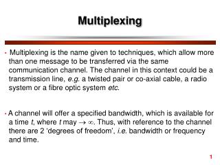
Multiplexing. Break one high-speed physical communication circuit into several lower-speed logical circuits Allows many different devices to use the circuit simultaneously while it seems that each pair of devices has the physical circuit all to itself Usually done in multiples of 4

E N D
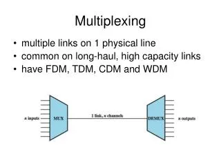
Multiplexing • Break one high-speed physical communication circuit into several lower-speed logical circuits • Allows many different devices to use the circuit simultaneously while it seems that each pair of devices has the physical circuit all to itself • Usually done in multiples of 4 • Two multiplexers are needed for a circuit – one to combine the original circuits into a multiplexed circuit and one to separate them back out into separate circuits • Four types of multiplexing • Frequency division multiplexing (FDM) • Time division multiplexing (TDM) • Statistical time division multiplexing (STDM) • Wavelength division multiplexing (WDM)
Frequency Division Multiplexing • Divides the circuit “horizontally” by assigning different frequencies (channels) to each logical circuit • All signals exist in the media at the same time on non-interfering frequencies • Available bandwidth is divided into channels and “guardbands” which separate the channels • Channels do not need to have identical capacities
Time Division Multiplexing • Divides the circuit “vertically” by allowing different devices to transmit on the circuit at different times • Devices take turns using the circuit to transmit data • Time is allocated to each device in turn, even if the device is idle • More efficient than Frequency Division Multiplexing, as there is no need for “guardbands” • The full capacity of the line is divided evenly among the multiplexed circuits
Statistical Time Division Multiplexing • Takes advantage of the fact that not all devices will be transmitting all the time • Multiplexed circuit bandwidth is typically smaller than the combined bandwidths of the individual circuits • Circuit capacity requirements are determined statistically by analyzing the usage of the circuits to be multiplexed • Given four 64kbps circuits, TDM would require a 256kbps multiplex circuit • If we find that, statistically, only two of the four circuits are typically active simultaneously, we can provision a 128kbps multiplex circuit using STDM • Provides more efficient use of bandwidth • Can cause time delay if all circuits become active simultaneously • Increased complexity and overhead, since each transmission must include an indication of the circuit it belongs to
Wavelength Division Multiplexing • A version of FDM used in fibre-optic cabling • Originally, fibre-optic transmission used a single “color” (light wavelength) for transmitting 622Mbps (622 million bits per second) • By attaching devices that transmit and detect different light wavelengths, multiple circuits can be multiplexed over a single fibre-optic cable • Dense Wave-Division Multiplexing (adding TDM to WDM) has increased the capacity of a single fibre-optic cable to 400 Billion bits per second • DWDM Experimental results over 1.5Tbps • 1,500,000,000,000 bits per second • Approximately 200 Gigabytes/second
Inverse Multiplexing (IMUX) • Opposite of multiplexing • Combines two or more low-speed circuits making them appear as a single high-speed circuit • Commonly used to provide T1 circuits in Wide Area Networks • Combines 24 low-speed (64kbps) circuits to create a single 1.544 Mbps circuit • IMUX equipment not standardized, so the same vendor should be used for both ends of the circuit • BONDING (Bandwidth on Demand Interoperability Networking Group) standards have been adopted by some vendors for using 6 separate ISDN links over six telephone lines for room-to-room teleconferencing
Digital Subscriber Line (DSL) • Provides high-speed data transmission over traditional telephone lines • Limitations on traditional phone lines is based in the telephone and switching equipment in the end offices • Actual cabling (local loop) is capable of much higher transmission capacity • Conversion from POTS to DSL involves changing end equipment, not rewiring the local loop, making it very cost effective • The customer premises equipment (CPE) includes a line splitter, which separates the traditional voice traffic from the data transmissions • The line splitter directs data transmissions into the DSL modem (also called a DSL router) which is both a modem and a Frequency Division Multiplexer • At the telephone company end office, the local loop enters into the Main Distribution Frame (MDF), which works like the line splitter on the customer premises • The MDF sends voice traffic to the voice telephone network, and sends DSL traffic to the DSL Access Multiplexer (DSLAM) • The DSLAM demultiplexes the data streams and converts them to ATM data which can be distributed to the Internet Service Provider (ISP) • The ISP’s Point of Presence (POP) can be co-located or located elsewhere
Asymmetric Digital Subscriber Line (ADSL) • Uses Frequency Division Multiplexing to create three separate channels over the one local loop circuit • One traditional voice circuit • One relatively high-speed simplex circuit from the end office to the customer premises • One slightly slower half-duplex circuit, primarily intended for upstream traffic from the customer premises to the end office • It is called asymmetric because each of the two data circuits have different capacities • Each of the two data channels can be further subdivided using Time Division Multiplexing • The size of the two digital channels depends on the distance from the CPE to the end office • Shorter distance to End Office results in less attenuation of the signal, allowing higher frequencies to be used and yielding a faster connection • Offering higher speed ADSL limits the number of potential customers, while offering lower speed decreases product attractiveness
Cable modems • Digital service offered by cable companies • Data over Cable Service Interface Specification (DOCSIS) is the dominant standard • Standard most often used by cable companies running hybrid fibre coax (HFC) networks • Architecture is very similar to DSL • Main difference is that DSL is point-to-point, while cable modems share multi-point circuits • Each user must compete with other users for the available capacity • All messages on the circuit go to all computers on the circuit • Cable TV circuit enters the customer premises through a cable splitter • TV signals are sent to the TV network • Data signals are sent to the cable modem (both a modem and an FDM) • Standard coaxial cable circuit may be shared by from 300 to 1000 customers • Not all of these cable TV customers will subscribe to high-speed internet • The coax runs to a fibre node with an optical-electrical converter • Each fibre node may service up to half a dozen cable circiuts • The fibre nodes are connected to a distribution hub (also called a headend) through two separate circuits • Upstream circuit connects to a cable modem termination system (CMTS) • Downstream circuit carries both ordinary cable TV signal and downstream traffic destined for the customer premises
Local Area Networks • Introduction • Why use a LAN? Dedicated servers vs. Peer-to-peer LANs • LAN Components • NICs, Cables, Hubs and Network Operating Systems • Traditional Ethernet (IEEE 802.3) • Topology, Media Access Control, Ethernet Types • Switched Ethernet • Topology, Media Access Control, Performance Benefits • Wireless LANs (IEEE 802.11) • Topology, Media Access Control, Wireless Ethernet Types • Other Wireless Technologies • Infrared Wireless, Bluetooth • Improving LAN Performance • Improving Server Performance, Improving Circuit Capacity, Reducing Network Demand
Why use a LAN? • There are two main benefits to using a local area network: information sharing and resource sharing. • Examples of information sharing include file sharing, exchanging e-mail, and using the Internet. • Examples of resource sharing include sharing hardware and software, such as sharing an expensive printer. • Another important resource sharing technique is to purchase software on a per seat basis. For example, only purchasing a 10-seat license for a software program on a 20 client network instead of purchasing 20 copies of the same program.
Dedicated Server Networks • A basic LAN dichotomy exists between dedicated server LANs and peer-to-peer LANs which don’t have servers. Since 90% of all LANs have a dedicated server, this chapter mostly focuses on server-based LANs. • A dedicated server is a computer that is permanently assigned a specific server task such as being a Web server, e-mail server, file server or printer server. • Servers also run a special operating system called a server network operating system. • When many servers are part of a network, it can be referred to as a server farm.
Peer-to-Peer Networks • Peer-to-peer networks do not use dedicated servers. • Any computer on a peer-to-peer network can act as both a client, accessing resources or information on other computers on the network, or as a server, allowing access to attached information or resources. • Peer-to-peer networks tend to be small networks. • The main advantage of peer-to-peer networking is lower cost since there is no dedicated server, generally the most expensive network component. • The main disadvantage is that peer-to-peer networks are generally slower than dedicated server networks, since each computer is less powerful and may be in use as a client and a server at the same time.
Basic LAN Components • The six basic LAN components are: 1. Clients 2. Servers 3. Network Interface Cards 4. Network Cables 5. Hubs and Switches 6. Network Operating System
Network Interface Cards • Network interface cards, also called network cards and network adapters include a cable socket allowing computers to be connected to the network. • NICs are part of both the physical and data link layer and include a unique data link layer address (sometimes called a MAC address), placed in them by their manufacturer. • Before sending data onto the network, the network card also organizes data into frames and then sends them out on the network. • Notebook computers often use NICs that are plugged into the PCMCIA port.
Network Cables • Each computer is physically connected to the network using a cable. • These cables are either untwisted wire pairs (UTP, the most common choice), shielded twisted pair (STP), coaxial cable, or optical fiber. • Wireless LANs use radio frequencies or infrared light instead of cables. • Sometimes two different types of cabling can be linked using a special connector. A BALUN (Balanced-Unbalanced) is one such device that connects UTP and Coaxial Cable.
Hubs • Hubs act as junction boxes, linking cables from several computers on a network. Hubs are usually sold with 4, 8, 16 or 24 ports. • Some hubs allow connection of more than one kind of cabling, such as UTP and coax. • Hubs also repeat (reconstruct and strengthen) incoming signals. This is important since all signals become weaker with distance. • The maximum LAN segment distance for a cable can therefore be extended using hubs.
Network Operating Systems • The NOS is the software that runs the LAN. It comes in two types: Server NOSs & Client NOSs. • Server NOSs enable server to execute and respond to the requests sent to them as web server, print servers, file servers, etc. • Client NOS functions are typically included in most OS packages such as Windows 98 and Windows 2000.
Network Profiles • The network profile specifies what resources on each server are available to the network for use by other computers, including data files, printers, etc. • Devices that are not included in the network profile can not be used over the network. • User profiles describe what each user on a LAN has access to. • Most LANs also use auditing software which keeps track of which user has accessed what network resource.
Ethernet (IEEE 802.3) • Almost all LANs today use Ethernet • Originally, Ethernet was jointly developed by a consortium of Digital Equipment Corp., Intel and Xerox and was standardized as IEEE 802.3. • Ethernet LANs that use hubs are sometimes called shared Ethernet.
Shared Ethernet Topology • Ethernet’s logical topology is a bus topology. • This means all computers on the network receive messages from all other computers, whether the message is intended for those computers or not. • When a frame is received by a computer, the first task is to read the frame’s destination address to see if the message is meant for it or not. • Although, a decade ago most Ethernet LANs used a physical bus, almost all Ethernets today use a physical star topology, with the network’s computers linked into hubs. • It is also common to link use multiple hubs to form more complex physical topologies
Media Access Control • Ethernet’s medium access control protocol, called CSMA/CD, is contention-based • With a contention-based protocol, frames can be sent by two computers on the same network at the same time, in which case they will collide and become garbled. • CSMA/CD, can thus be termed “ordered chaos” because it tolerates, rather than avoids, collisions caused by two computers transmitting at the same time.
CSMA/CD • Stands for: Carrier Sense Multiple Access w/ Collision Detect • Carrier Sense: computers listen to the network to see if another computer is transmitting before sending anything themselves. • Multiple Access:all computers have access to the network medium. • Collision Detect:if they detect a collision (CD), they then wait a random amount of time and resend the frame (It has to be random in order to avoid another collision).
Ethernet Physical Media Standards • Ethernet Media are formatted as follows: [Value1]Base/Broad[Value2] • Value 1: Data Rate for Medium 10 = 10Mbps • Base or Broad • Base = Baseband Mode meaning only one (digital) channel • Broad = Broadband (analog) cable transmissions use more than one channel (e.g., cable TV) • Value2: (relates to maximum distance possible in hundreds of meters or cable type T= twisted pair, F =fiber)
Types of Ethernet • Seven types of shared Ethernet have been in use: • 10Base5 = thick Ethernet, uses thick coax. This is the original Ethernet specification. Now uncommon. • 10Base2 = thin Ethernet, uses thin coax. Became popular in the early 1990s as a cheaper alternative to 10Base5. Now uncommon. • 10BaseT = twisted pair Ethernet, most common type of Ethernet. Uses Cat 3 and Cat 5 UTP. Common but rapidly losing ground to 100BaseT. • 100BaseT = also called Fast Ethernet, has replaced 10BaseT in sales volume. Uses Cat 5 UTP (Sometimes combined 10/100 Ethernet is found in which some segments run 10BaseT and some run 100BaseT is also used by some organizations). • 1000BaseT = Gigabit Ethernet. Maximum cable length is only 100 meters. • 10GbE = 10 Gbps Ethernet. Uses fiber and is typically full duplex. • 40GbE = 40 Gbps Ethernet. Uses fiber and is typically full duplex.
1. Name Maximum Data Rate Cables 10Base5 10 Mbps Coaxial 10Base2 10 Mbps Coaxial 10BaseT 10 Mbps UTP cat 3, UTP cat 5 100BaseT 100 Mbps UTP cat 5, fiber 1000BaseX 1 Gbps UTP cat 5, UTP cat 5e, UTP cat 6, fiber 10 GbE 10 Gbps UTP cat 5e, UTP cat 6, UTP cat 7, fiber 40 GbE 40 Gbps fiber Types of Ethernet
Switched Ethernet Topology • Switched Ethernet uses switches instead of hubs. • While a hub broadcasts frames to all ports, the switch reads the destination address of the frame and only sends it to the corresponding port. • The effect is to turn the network into a group of point-to-point circuits and to change the logical topology of the network from a bus to a star.
Basic Switch Operation • Switches make forwarding decisions based on forwarding tables (similar to routing tables). • When a frame is received, the switch reads its [data link layer] destination address and sends the frame out the corresponding port in its forwarding table. • Switches making switching decisions based on data link layer addresses are called layer-2 switches. • When a switch is first turned on, its forwarding table is empty. It then learns which ports correspond to which computers by reading the source addresses of the incoming frames along with the port number that the frame arrived on. • If the switch’s forwarding table does not have the destination address of the frame, it broadcasts the frame to all ports. • Thus, a switch starts by working like a hub and then works more and more as a switch as it fills its forwarding table.
Media Access Control • Switched Ethernet still uses CSMA/CD media access control, but collisions are less likely as each network segment operates independently. • The network’s modified topology also allows multiple messages to be sent at one time. • For example, computer A can send a message to computer B at the same time that computer C sends one to computer D. • If two computers send frames to the same destination at the same time, the switch stores the second frame in memory until it has finished sending the first, then forwards the second.
Performance Benefits • Switched Ethernet can dramatically improve network performance. • Shared Ethernet 10BaseT networks are only capable of using about 50% of capacity before collisions are a problem • Switched Ethernet, however, runs at up to 95% capacity on 10BaseT. • Another performance improvement can be made by using a 10/100 switch that uses a 100BaseT connection for the server(s) and/or routers, i.e., the network segments experiencing the highest volume of LAN traffic.
Wireless Ethernet (IEEE 802.11) • Wireless LANs dispense with cables and use radio or infrared frequencies to transmit signals through the air. • WLANs are growing in popularity because they eliminate cabling and facilitate network access from a variety of locations and for mobile workers (as in a hospital). • The most common wireless networking standard is IEEE 802.11, often called Wireless Ethernet or Wireless LAN.
Wireless LAN Topology • WLAN topologies are the same as on Ethernet: physical star, logical bus • Wireless LAN devices use the same radio frequencies, so they must take turns using the network. • Instead of hubs, WLANs use devices called access points (AP). Maximum transmission range is about 100-500 feet. Usually a set of APs are installed making wireless access possible in several areas in a building or corporate campus. • Each WLAN computer uses an NIC that transmits radio signals to the AP. • Because of the ease of access, security is a potential problem, so IEEE 802.11 uses 40-bit data encryption to prevent eavesdropping.
A wireless Ethernet access point connected into an Ethernet Switch.
WLAN Media Access Control • Wireless LANs use CSMA/CA where CA = collision avoidance (CA). With CA, a station waits until another station is finished transmitting plus an additional random period of time before sending anything. • Two different WLAN MAC techniques are now in use: the Physical Carrier Sense Method and the Virtual Carrier Sense Method.
Physical Carrier Sense Method • In the physical carrier sense method, a node that wants to send first listens to make sure that the transmitting node has finished, then waits a period of time longer. • Each frame is sent using the Stop and Wait ARQ, so by waiting, the listening node can detect that the sending node has finished and can then begin sending its transmission. • With Wireless LANs, ACK/NAK signals are sent a short time after a frame is received, while stations wishing to send a frame wait a somewhat longer time, ensuring that no collision will occur.
Virtual Carrier Sense Method • When a computer on a Wireless LAN is near the transmission limits of the AP at one end and another computer is near the transmission limits at the other end of the AP’s range, both computers may be able to transmit to the AP, but can not detect each other’s signals. • This is known as the hidden node problem. When it occurs, the physical carrier sense method will not work. • The virtual carrier sense method solves this problem by having a transmitting station first send a request to send (RTS) signal to the AP. If the AP responds with a clear to send (CTS) signal, the computer wishing to send a frame can then begin transmitting.
Types of Wireless Ethernet • Two forms of the IEEE 802.11b standard currently exist, utilizing the 2.5 GHz band: • Direct Sequence Spread Spectrum (DSSS) uses the entire frequency band to transmit information. DSSS is capable of data rates of up to 11 Mbps with fallback rates of 5.5, 2 and 1 Mbps. Lower rates are used when interference or congestion occurs. • Frequency Hopping Spread Spectrum (FHSS) divides the frequency band into a series of channels and then changes its frequency channel about every half a second, using a pseudorandom sequence. FHSS is more secure, but is only capable of data rates of 1 or 2 Mbps. • IEEE 802.11a uses Orthogonal Frequency Division Multiplexing (OFDM), operates in the 5 GHz band with data rates of up to 54 Mbps. • IEEE 802.11g uses OFDM in the 2.5 GHz band, operates at up to 54 Mbps, and is compatible with 802.11b
Infrared Wireless LANs • Infrared WLANs are less flexible than IEEE 802.11 WLANs because, as with TV remote controls that are also infrared based, they require line of sight to work. • Infrared Hubs and NICs are usually mounted in fixed positions to ensure they will hit their targets. • The main advantage of infrared WLANs is reduced wiring. • A new version, called diffuse infrared, operates without a direct line of sight by bouncing the infrared signal off of walls, but is only able to operate within a single room and at distances of only about 50-75 feet.
Bluetooth • Bluetooth is a 1 Mbps wireless standard developed for piconets, small personal or home networks. • It may soon be standardized as IEEE 802.15. • Although Bluetooth uses the same 2.4 GHz band as Wireless LANs it is not compatible with the IEEE 802.11 standard and so can not be used in locations that use the Wireless LANs. • Bluetooth’s controlled MAC technique uses a master device that polls up to 8 “slave” devices. • Examples of Bluetooth applications include; linking a wireless mouse, a telephone headset, or a Palm handheld computer to a home network.
Improving LAN Performance • As networks become more and more intensively used, LAN performance becomes a critical issue. • The measure of LAN Performance is throughput, i.e., the total amount of user data transmitted in a given period of time. • LAN performance can be improved by identifying and eliminating bottlenecks, that is, points in the network where congestion is occurring because the network or device can’t handle all of the demand it is experiencing.
Identifying Network Bottlenecks • Two common network bottlenecks are related to server access: • If server performance is poor when server utilization is high (>60%), then the bottleneck is the server. • If server performance is poor during periods of low server utilization (<40%), then the bottleneck is not the server but the network circuit.
Improving Server Performance • Two types of server performance improvements are possible: • Software improvements such as choosing a faster Network Operating System, fine tuning network and NOS parameters for optimal performance. • Hardware improvements such as adding a second server, upgrading the server’s CPU, increasing its memory space, adding more hard drives or adding a second NIC to the server.
Improving Server Performance: RAID • Improving disk drive performance is especially important, since disk reads are the slowest task the server needs to do. • Replacing one large drive with many small ones can improve server performance. • RAID or Redundant Array of Inexpensive Disks, builds on this idea. RAID system can be used to both improve performance and increase reliability by building redundancy into the hard drives, so that a hard drive failure does not result in any loss of data.
Improving Circuit Capacity • Improving circuit capacity can be done simply by upgrading one or all segments of a network to a faster protocol (which also means upgrading the NICs), such as; • Upgrading the network from 10BaseT to 100BaseT, or • Upgrading the network segment to the server from 10BaseT to 100BaseT • Another approach to improving circuit capacity is by increasing the number of network segments to the server. Most servers can handle several network segments simply by adding additional NIC cards, thereby increasing access to the server