Download
1 / 14
170 likes | 663 Views
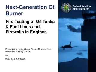
Next-Generation Oil Burner. Fire Testing of Oil Tanks & Fuel Lines and Firewalls in Engines. Motivation. Need for new test apparatus Specified burner, Park DPL 3400, no longer in production Inconsistencies in burner performance Reproducibility of experiment critical for compliance

E N D
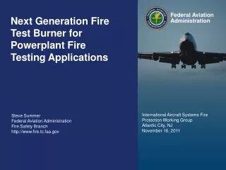
Next-Generation Oil Burner Fire Testing of Oil Tanks & Fuel Lines and Firewalls in Engines
Motivation • Need for new test apparatus • Specified burner, Park DPL 3400, no longer in production • Inconsistencies in burner performance • Reproducibility of experiment critical for compliance • Burner performance dependent upon several factors • Electric motor • Supply voltage differences and fluctuations • Does motor/fan supply constant, steady flow rate of air? • Variability in construction • Flange-type burners • Socket-type burners • Differences in blower castings • Laboratory conditions • Local air temperature, humidity affect supply air density, fuel to air mass ratio
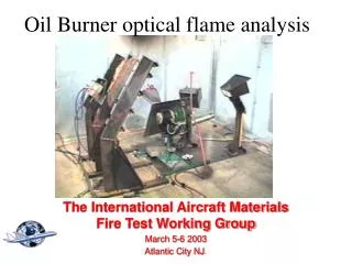
Operation of Oil Burner • Simple design • Airflow is mixed with fuel spray • Air/fuel mixture is ignited with high energy spark
Problems • Remove dependence upon electric motor What does the motor do? • Directs lab air through the blower housing and draft tube towards the sample at a fixed velocity/flow rate • Pressurizes liquid fuel to approx. 100 psi, which is required for Monarch-type fuel nozzles
Replacement of Electric Motor • Task 1: To supply air to the draft tube at a controllable velocity / flow rate • Solution: Utilize compressed air from laboratory compressor • More control over level of conditioning of supply air • Humidity • Temperature • Pressure • Flow can be metered with a sonic choke to deliver a constant mass flow rate of air • Mass flow rate will be fixed for choked flow • Choked flow for positive pressure conditions can be achieved by maintaining a constant inlet pressure and certain range of backpressures • Required parts / instrumentation: • Sonic choke • Precision air pressure regulator (moderate to high flow) • Pressure gauge (0-200 psig) and transducer to measure and record sonic choke inlet pressure • Solenoid valve to remotely operate the compressed air supply • Type-K thermocouple for inlet air temperature
Replacement of Electric Motor • Task 2: To supply the fuel rail / nozzle with fuel (JP-8) at an adjustable pressure • Solution: Construct a pressurized fuel tank • Fill partially with JP-8 • Pressurize the headspace with compressed N2 from gas bottle with pressure regulator • Required parts / instrumentation: • Pressure vessel • Pressure gauge and transducer to monitor fuel pressure • Bleed valve to reduce pressure • Compressed nitrogen and bottle regulator • Liquid level sight gauge to monitor fuel level • Solenoid valves for remote operation of fuel flow and fuel tank pressurization
NexGen Burner Concept • Initial Concept: • Compressed air metered with a sonic nozzle (critical flow venturi) • Fuel provided by a pressurized fuel tank • Utilize the original Park draft tube components • Stator • Igniters • Nozzle • Turbulator • By using the same components and matching the air velocity and fuel flow rate, the overall character of the flame is unchanged
NexGen Burner Design Pressure Regulator Fuel Nozzle Cone Draft Tube Stator Muffler Igniters Housing Sonic Orifice Turbulator Cradle
Pressurized Fuel System Pressure Regulator (in the range of 0-150 psig) e.g., Bellofram Type 70 Pressure Regulator, 2-150 psig, max 250 psig inlet, approx $79 Solenoid or manual ball valve Solenoid or manual ball valve Needle valve to control venting Pressurized Air Inlet Fuel Fill Vent to lab or outdoors Compressed gas (from bottled Nitrogen or Air, or air compressor, if it is capable Vent Pressure Vessel (for example, McMaster-Carr p/n 1584K7, ASME-Code Vertical Pressure Tank W/O Top Plate, 15 Gallon Capacity, 12" Dia X 33" L, $278.69) or any suitable pressure vessel that can withstand pressures of around 150 psig. High pressure liquid level sight gauge (We use McMaster Carr p/n: 3706K23) Air/N2 @ ~120 psig Fuel This schematic is pretty basic. You can supplement this design with whatever instrumentation you would like to obtain the required data or to make for easier operation. Some examples would be a pressure transducer, remotely operated solenoid valves, fuel flow meter, etc. Fuel Outlet Nozzle 5.5 GPH 80 deg-PL Solenoid or manual ball valve Ice Bath H2O
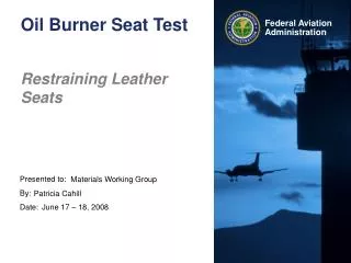
Burner Adjustments • The burner can be adjusted for various applications • Combined adjustments of air and fuel flow rates can be made to achieve calibration for the specific test • Powerplant Hose Assemblies and Fire Penetration Tests • 2.0 gph-rated fuel nozzle • 2000°F avg flame temperature • 9.3 BTU/ft2s measured heat flux
Inlet Conditions • Burner inlet air and fuel can be conditioned to strictly control burner parameters • A heat exchange system can be constructed to reduce fluctuations in inlet air and fuel temperature to +/- 10°F
Heat Exchange System Water Pump Condensate Separator McMaster-Carr p/n 43775K55 Cooler w/ice water Air From Compressor Burner Heat Exchanger McMaster-Carr p/n 3865K78 Blue = Water Lines Orange = Fuel Lines Black = Air Lines Fuel Tank
Ice Bath Fuel Cooling Fuel in/out Air Cooling Water in/out Ice / Water Mixture Insulated Beverage Cooler 72 qt. capacity
Proof of Concept • NexGen burner was initially designed for testing thermal acoustic insulation burnthrough resistance • The burner was compared to the Park DPL 3400 burner that is specified in Title 14 CFR 25.856(b) • Fuel flow 6.0 gph • Airflow 66 SCFM • Flame Temperature 1900°F ±100°F • When testing the same materials, the NexGen burner gave similar results to that of the Park burner • Multiple burners were constructed and tested, all providing similar results • Some burners were shipped to laboratories around the world, and also gave results similar to those obtained at the FAA Tech Center • Currently, the same procedure is being followed to use the NexGen burner for fire testing of seat cushions