Download
1 / 36
360 likes | 373 Views
LHC Collimation Review 2013 May 30 th -31 st , 2013 CERN, Geneva, Switzerland. Introduction to dispersion suppressor collimation. Stefano Redaelli for the collimation team Inputs from: G. Arduini, R. Bruce, O. Brüning, F. Cerutti, J. Jowett, B. Salvachua, A. Verweij, and many other people.

E N D
LHC Collimation Review 2013 May 30th-31st, 2013 CERN, Geneva, Switzerland Introduction to dispersion suppressor collimation • Stefano Redaelli for the collimation team • Inputs from: G. Arduini, R. Bruce, O. Brüning, F. Cerutti, J. Jowett, B. Salvachua, A. Verweij, and many other people.
Outline • Introduction • Present LHC collimation • DS collimation concept • Scope of this review • Ongoing LS1 upgrades • Conclusions
Superconducting coil: T = 1.9 K, quench limit ~ 15mJ/cm3 Proton beam: 145 MJ (LHC design: 362 MJ) (HL-LHC: 500MJ!) Factor 9.7 x 10 9 Aperture: r = 17/22 mm Introduction LHC “Run 1” 2010-2013: No quench with circulating beam, with stored energies up to 70 times of previous state-of-the-art!
The LHC collimator 1.0m+0.2m tapering
500MJ R. Assmann et al. (2003) Requirements to handle 360 MJ Requirements to handle 360 MJ Main collimation challenges:- High stored energy: Collimators needed in all phases(inj., ramp, squeeze, physics); Function-driven controls of jaw positions mandatory;Robustness and cleaningefficiency; Big and distributed system (100 collimators). - Small gaps: Mechanical precision, reproducibility (< 20 microns); Constraints on orbit/optics reproducibility; Machine impedance and beam instabilities. - Collimator hierarchy: Collimators determine the LHC β* reach. - Machine protection: Redundant interlocks of collimator jaw positions and gaps. - High-radiation environ.: Radiation-hard components (HW + SW); Challenging remote handling, design for quick installation.
Multi-stage cleaning at the LHC • Based on “bulk” amorphous jaws. Different materials: CFC, W, Cu, graphite. • The multi-stage collimation keeps leakage to sensitive equipment at safe levels. • Define of local collimation cleaning inefficiency: ηc = ΔNlost / Nabs * 1 / ΔsApproximated in measurements by ratio of BLM signals to losses at primaries. • Cold magnets: must stay below their quench limit.Cold losses, ηc * Ntot / τb, in case of bad beam lifetime (τb) must be below quench limit Rq • Other important role of the collimation system: minimize radiation doses to equipment. • Minimize radiation doses on warm magnets in IR3/7 [not discusses in this review]. • Robust system providing excellent passive protection in case of failures.
Present LHC collimation layout Two warm cleaning insertions, 3 collimation planes IR3: Momentum cleaning 1 primary (H) 4 secondary (H) 4 shower abs. (H,V) IR7: Betatron cleaning 3 primary (H,V,S) 11 secondary (H,V,S) 5 shower abs. (H,V) Local cleaning at triplets8 tertiary (2 per IP) Momentum cleaning Betatron cleaning Passive absorbers for warm magnets Physics debris absorbers Transfer lines (13 collimators)Injection and dump protection (10) Total of 108 collimators (100 movable). Two jaws (4 motors) per collimator! Full system commissioned in 2010! Picture by C. Bracco
1/10000 0.00001 0.000001 Collimation cleaning at 4 TeV (β*=60cm) Betatron Beam 1 Dump Off-momentum TCTs TCTs Cleaning inefficiency [BLM/BLMtcp] TCTs TCTs B. Salvachua Highest COLD loss location: inefficiency < 1e-4. For most of the cold aperture it is actually < 1e-5! 2012-13: “tight” collimator settings (TCP gaps as at 7 TeV) for higher beta*! 60 cm for protons, 80cm for ions.
Loss maps in IR7 Beam 1 1/10000 B. Salvachua Critical location (both beams): losses in the dispersion suppressor (highest at the Q8) from single diffractive interactions with the primary collimators. No other significant limitation have been observed so far from collimation cleaning. Do the critical cleaning locations also limit the LHC and HL-LHC performance?
~1/100 Betatron cleaning with Lead ions B. Salvachua B. Salvachua Experience at 4 TeV with Pb-p beams confirmed the results at 3.5 TeV: IR7 cleaning in the order of a few percents for ion beams! Present collimation not optimized for ions!
Outline • Introduction • Present LHC collimation • DS collimation concept • Scope of this review • Ongoing LS1 upgrades • Conclusions
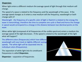
βy βx Dx Energy loss from single-diffractive interactions with the TCP (SixTrack, D. Mirarchi) Dispersion suppressor losses Warm dogleg Warm straight section Cold DS + arc • Particles that change rigidity (e.g. lose energy) in a straight insertion are lost in the dispersion suppressor (DS): this is the first location with high dispersion. • Cleaning insertions (IR3/7): proton mainly lose energy due to single-diffractive interactions with the primaries†. • Experimental regions (IR1/2/5/8): protons lose energy in the collision process. • Different physics for ions: similar qualitative behaviour due to rigidity change. • Collimators are in the straight section: first dipoles in the DS act as spectrometers. • No local protection available in the DS. IR7 The present LHC collimation system cannot protect efficiently the DS! This limitation predicted by simulations is confirmed by the operational experience(DS’s are the highest cold loss locations). † IR3: dispersion not zero but optimized to have TCP’s as bottleneck -> same problem
DS limitation (1): halo cleaning Minimum (assumed) beam lifetime Quench limit of SC magnets LHC total intensity reach from collimation Collimation cleaning at limiting cold location • 7 TeV extrapolations are scaled from measurements of achieved losses in dedicated quench tests and measured and simulated collimation cleaning.- Important: uncertainty on beam lifetime at higher energies. • 7 TeV intensity reach:9.9 x 10¹⁴ p for minimum lifetime of 0.2h- This is about 3 times nominal (1.15e11/bunch); 1.5 times HL-LHC (2.2e11/b)- Assumes tight settings and “pessimistic” lifetime from observations in 2012 - More realistic lifetime assumptions: 0.5-1.0 h (best beam) give more margin! - Next talks: quench limits, lifetime, interplay stability/beta*/number of dumps • No new inputs for ion operation: a quench tests could not be performed! - See talk by J. Jowett. • With the given uncertainties, it is important to keep the option to assess these assumptionswith operational experience at energiesclose to 7 TeV. Need feedback from the review: Safety factors appropriate? Correct assumptions on lifetime?
DS limitation (2): physics debris IR1 Talk A. Marsili IR2 • Losses seen in the whole experimental insertion and DS from collision products. • IR1/5 (high luminosity): concerns for matching quadrupoles, Q5 in particular. • Possible concerns: peak DS losses when establishing collisions as well as total doses due to long physics runs. • Different pattern for proton and ions - details in talks by A. Marsili and J. Jowett. Talk J. Jowett
Comment on losses during the cycle • Our present understanding: • Quenches in the cleaning insertions (e.g., IR7 DS) depends on total beam intensity; • Quenches in the experimental regions’ DSs depend on peak luminosity; • Radiation doses in all IRs depend on integrated luminosity. TCP-B2 Q9-L1 Q8-L7 See losses in a typical cycle (F3202, L=7e33cm-2s-1, I~2.2e14p): loss spikes during setup (injection, ramp, squeeze, collision setup). Loss at a TCP and at two limiting cold locations in IR7 and IR1.
Comparison to peak losses during4 TeV quench tests (without quench) Losses in a typical cycle Achieved losses in Q8-L7 during quench test! TCP-B2 Q8-L7 Q9-L1
Summary of DS collimation needs Scope of this review! “Dynamic” table that might evolve during this review... Complex parameter space that will be presented in the next talks. Goal for the collimation project at this stage: we want to have solution available to address possible issues revealed by the operational experience at ~7 TeV. Decide then on which IR the priority should be put on. Larger uncertainties for HL-LHC era, but more time to freeze layouts.
Do we have alternatives? DS collimation solution poses important technological challenges but otherwise is a robust solution that provides the required cleaning (several talks on that).Local cleaning in DS works both for cleaning and experimental insertions! Other possibilities exist on paper. Can they be ready for implementation in LS2? Note that the option to move magnets (see later) remains on the table! These alternatives require conceptual studies and beam tests before being considered as a valuable alternative for LS2. In additional, there is no obvious cure for the experimental regions. These ongoing studies are therefore not part on the review mandate. Studies/beam test program ongoing for HL-LHC.
Outline • Introduction • Present LHC collimation • DS collimation concept • Scope of this review • Ongoing LS1 upgrades • Conclusions
V. Parma et al. Baseline for DS collimation until 2011 • Concept of IR3 “combined cleaning”:- 2 DS collimators in IR3 - Add vertical secondaries to achieve betatron and momentum cleaning • Cleaning not ideal but sufficient until LS2, IR7 upgrade would come later. • Involved moving magnets between Q7 and Q11 at either side of IR3. • Motivation: IR3 more radiation tolerant and DS easier to modify. • In 2011, following also the recommendation of the review, it was decided to postpone the important works for the IR3 combined system: Acceptably small risk of seeing performance limited between LS1 and LS2 compared to risk taken in changing layout Significant manpower involved for moving magnets • Encouraged to prepare for implementation in LS2+, profiting of 11T dipole research • Why another review now?
What has changed?(only aspects relevant for DS collimation) • More operational experience: could handle 140MJ beams! • Confirmed the collimation performance with “tight” settings, understand better the hierarchy setting limits.- More insight on the interplay between β*reach and impedance limits • New quench tests: we raised the lower quench limit estimate - Still no quench with losses 3-10 times larger than 2011! • BUT: we experienced a worsening of beam lifetime for smaller β* operation with tight collimator settings. - Lost more than a factor 20 compared to 2011; - Now losses during whole cycle and not only when bringing beam in collision • The option of the temporary IR3 combined cleaning is dismissed. We consider instead one single solution for HL-LHC.- 11T dipoles would ease the implementation in IR7, if needed. - IR7 will be more radiation tolerant thanks to electronic relocation - No talk scheduled on that unless requested by review panel! • Important experience on IR debris cleaning for protons- New TCL collimator layout proposed! • Decision on warm vs cold DS collimator made for LS2 timeline • Planned ALICE upgrade for 6x1027cm-2s-1
Scope and mandate • I think that major decisions on the DS modification for high intensity proton operation should be taken after some experience at 6.5-7 TeV • Can we decide now about implementation for ion operation? • What do we need to do in the next ~2 years in order to make sure that in 2015 we will have all the technical background to decide on the DS collimation, if needed? • Are there viable alternatives to the scheme based on the 11T dipoles?
A look at the program • Outlook of HL-LHC collimation studies in one single talk in S4 • “Social” program:Visit of collimation workshops on Wed. and review dinner on Thu. • Three main sessions:S1. Introduction and review scopeThe HL-LHC timeline - L. Rossi Introduction to DS collimation - S. RedaelliPresent LHC collimator - R. Losito S2. Estimated performance reach at > 6.5 TeVCleaning performance - B. SalvachuaSetting limits and beta* reach - R. BruceImpedance - N. MounetCollimation cleaning with ATS optics for HL-LHC - A. MarsiliDS collimation for heavy-ion operation - J. JowettEnergy deposition simulations for quench tests - E. SkordisQuench limits: extrapolation of quench tests to 7 TeV - A. VerweijOverview of quench limits for faster time ranges - M. SapinskiS4. Status of DS collimation implementationWhat do we need to decide now to have Nb3Sn dipoles in LS2? - L. BotturaStatus of 11T dipole program - M. KarppinenCryogenics design choices and integration issues - V. ParmaStatus of the TCLD collimator design - A. BertarelliHeat load scenarios and protection levels for ions - G. Steele Many thanks to Julia D. for the help in the organization! Feel free to contact her, Lucio or myself in case of any issue! Many thanks to all speakers!
Outline • Introduction • Present LHC collimation • DS collimation concept • Scope of this review • Ongoing LS1 upgrades • Conclusions
LS1 Collimation operational experience • Very good performance of the collimation system so far (up to 140MJ): - Validated all critical design choices (HW, SW, interlocking, ...); - Cleaning close to simulations and ok for operation after LS1; - We learned that we can rely on the machine stability! - Established and improved semi-automatic alignment tools; - Performance estimates based on 2011 quench tests - to be reviewed at the end of 2012. • The present LHC collimation cannot protect the cold dispersion suppressors.- Critical locations with present layout: IR7, IR1/5, IR2 (ions). - Investigations ongoing on limitations from quench and magnet lifetime. • The collimators determine the LHC impedance- Rich program on “dream” materials and new collimator concepts. • Collimation alignments and validation of new setting are time-consuming. • The operation flexibility in the experimental regions (VdM scans, spectrometer polarity changes, β* leveling, ...) is affected by collimation constraints. • The β* reach is determined by collimation constraints: retraction between beam dump and horizontal TCTswhich are not robust. • Collimator handling in radiation environment will be challenging.
The 16 Tungsten TCTs (industrial production) in all IRs and the 2 Carbon TCSGs in IR6 (in-house production) will be replaced bynew collimators with integrated BPMs. Tests in the SPS with mock-up collimator very successfulGain: can re-align dynamically during standard fills. No need for special low-intensity fills ➙ Drastically reduced setup time(gain of a factor ~100) => more flexibility in IR configurations ➙ Improved monitoring of TCT centres in the IRs (reduce validation time)! ➙ Reduced orbit margins in cleaning hierarchy => more room to squeeze β*(see R. Bruce’s talk) Other system improvements ongoing: ➙ Improved layout in IR8 (better impedance); ➙ Additional passive absorbers in IR3 to increase the warm magnet lifetime; ➙ Improved TCL layouts in IR1/5 for better absorption of physics debris. BPM buttons Courtesy O. Aberle, A. Bertarelli, F. Carra, A. Dallocchio, L. Gentini et al. D. Wollmann et al.: HB2012 LHC collimation after LS1
A. Marsili Solution of limitations in IR1/5 Losses in the IR5 DSfor L=1034cm-2s-1 • Baseline layout to improve debris losses with “TCL” collimators proposed for implementation in LS1 alread- S. Redaelli, LMC Nov. 7th, 2012. • Present layout: 1 TCL in cell 5 (TCL-5) • New layout: add TCL-4 and TCL-6 • With TCL-4, losses below 1 mW/cm3, i.e. more than a factor 10 below quench limit! • Sufficient margin for the operation until LS3 with peak luminosity below 3x1034! • Further gain by factor > 50 with TCL-6 expected in DS. • Caveats:- Ongoing comparison with 4 TeV measurements to improve understanding- Loss distributions with new TCLs need assessment against R2E requirements- Operationally, need to synchronize with need of forward physics community IR5 L. Esposito
Conclusions • The present collimation system was introduced • The achieved collimation performance was reviewed and the concerns on dispersion suppressor (DS) losses introduced. - The LHC and the collimation system worked very well (140MJ; ~30fb-1)! - The present LHC collimation cannot protect efficiently the DS’s - Is this going to induce a performance limitation for the LHC and HL-LHC? • We ask advice to an external review panel on whether we are on good track to address potential performance limitations revealed by the LHC operation in 2015 at energies close to 7 TeV. - The overall performance is very encouraging, but we want to be sure that future performance limitations are excluded with appropriate margins- Our goal is to be ready for actions in LS2 if needed. • If available in time, the 11 T dipoles would provide an elegant and “transparent” solution, “easily” applicable to several IR’s- Can we have a solution bases on this technology for possible actions in LS2? • Other upgrade studies will be presented at the end of this review!
Losses from luminosity debris Proton operation in 2012 Proton operation in 2011 MQX 10-4 Q4/Q6 Q8 Q9 Q9 Ongoing program (beam measurements + tracking and energy deposition simulations) followed up by the ColUSM to understand the present losses from luminosity debris ➙ feedback on layout of experimental regions.
Q8-BLM2 Q8-BLM1 Q8-BLM3 Q7 Measurements of TCL scans in IR1/5 Gap scans with the physics debris collimators (TCLs) in IR1/5: direct measurements of loads in matching section and DS; simulation benchmark. Immediate interest: update of IR1/5 layout during LS1! Q7 Q8 Q9 Q10 Proposal to perform cryogenics measurements in standard physics fills in different conditions. See also talk by F. Cerutti at the CWG, Aug. 2012. A. Marsili
2011 ± 1.05 mm from the 140 MJ beam! 2012 Comparison: 2011 vs 2012 2011 2012 The local cleaning in the IR7 DS’s was improved by afactor ~5 compared to 2011. Improvements from 2011 driven by the deployment of collimator“tight” settings.(TCP settings equivalent to 7 TeV nominal gaps), studies in MDs in 2011. Drawbacks: we are now dealing with larger losses in standard operation: tail removal during ramp and beam instabilities from larger impedance!
Number of dump triggered during collimator align. Only major alignments shown here 1.0 Hz 12.5 Hz Movements 8.0 Hz BLM Feedback No Automation 12.5 Hz BLM 8Hz motion Collimator alignment 2012 commissioning: alignment campaigns Ph.D. work of G. Valentino See a recent ICAP + HB2012 papers
Scope of collimation upgrades • Improve the cleaning performance- System limitations: dispersion suppressors (DS’s) of cleaning (IR3/7) and experimental (IR1/2/5) regions • Improve impedance and robustness- State-of-the-art new material and new designs for secondary collimator jaws - Improved robustness at critical locations (like TCTs) • Operational efficiency / machine protection aspects- Improve beta* reach and setting monitoring- Faster collimator alignment; improved accuracy - More flexibility for machine configurations (experimental regions) - Reduce sensitivity on orbit jitters and other machine perturbations • Be ready to replace collimators if they brake or age - The hardware is designed for 10 y lifetime • Achieve remote handling in high radiation environment- Quick collimator replacement in hottest LHC locations • New layouts in experimental regions for HL-LHC- Re-think IR1/5 collimation for new optics options/constrains • New injection / dump collimation → Injection&dump team Here: just review cleaning aspects that can be addressed by the dispersion suppressor collimators.
Upgrade strategy (I) • Shutdowns 2010-11 and 2011-12(See talk at Chamonix 2011)- New IR2 layout for improved ALICE data taking. - Software for faster and more robust collimator alignment.- Improved protection strategy (β* limits). - Improved controls HW: OP efficiency against downtimes from radiation. • LS1 (LHC energy to nominal)- BPM-integrated design in experimental and dump regions. (16 tertiary and 2 secondary) → Faster alignment in the IP’s, smaller β*, improved machine protection. - New IP8 layout (to allow installation of TCTs with BPMs). - Considering new passive absorbers in IP3 (longer lifetime of warm magnets). - Replacement of electronics components to improve redundancy. - Update the air duct in the cleaning insertion. Modified version of what was presented at Chamonix 2012.
Upgrade strategy (II) • LS2 (double LHC luminosity)- Possible first upgrade of experimental regions: DS collimators. - Additional collimators equipped with BPMs (faster alignment, better protection). - Improved design and new materials (less impedance, more robustness). - Possible implementation of hollow e-lens as beam scraper. - Investigate collimator HW aging / lifetime. - Remote handling (partly). • LS3 (HL-LHC)- Re-design of collimator layout in the experiments regions. (DS collimators + additional local protection for ATS optics). - Complete DS collimation in all the required IRs (also IR3/7 if needed). - New collimator materials to replace collimators that have aged. BPM design. - Fully remote handling in radiation environment. - New concepts for improved cleaning (crystal, hollow e-lens) - if needed. Modified version of what was presented at Chamonix 2012.