Download
1 / 41
410 likes | 538 Views
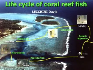
Dispersion-suppressor upgrade in IR3. V.Parma, CERN, TE-MSC. On behalf of the Dispersion Suppressor collimator project team:

E N D
Dispersion-suppressor upgrade in IR3 V.Parma, CERN, TE-MSC • On behalf of the Dispersion Suppressor collimator project team: • R.Assmann, V.Baglin, M.Bajko, P.Bestman, A.Bertarelli, C.Bertone, N.Bourcey, J.Coupard, S.Chemli, K.Dahlerup-Petersen, J.C.Guillaume, Y.Muttoni, D.Ramos, A.Perin, J.Ph.Tock, R.Van Weelderen, A.Vande Craen, R.Principe, A.Rossi, S.Russenchuck, ...and many others LHC Collimation Review 2011, CERN 14-15 June 2011
Outline • DS Collimators in IR3: description, implications • Organization and cost estimate • Changes to technical systems (cryogenics, vacuum, powering…) • Hardware modifications and status: • New equipment • Tunnel integration issues • Schedule • Summary and Outlook LHC Collimation Review 2011, CERN 14-15 June 2011
DS collimators: Leftside of point 3 ~ 200 m IP3 R33 RZ33 R34 11L3 10L3 9L3 8L3 7L3 QRL Q10 Q7 Q11 Q9 Q8 DQS Conn.cryostat DFBA TCLA BTVM 4’500 mm 4’500 mm 46 mm QRL Q10 Q7 Q11 Q9 Q8 DQS DFBA TCLA BTVM New Collimatorassembly (LTC) New Collimatorassembly (LTC) Short Conn.cryostat LHC Collimation Review 2011, CERN 14-15 June 2011
DS collimators: Right side of point 3 ~ 200 m IP3 R37 R38 7L3 8L3 9L3 10L3 11L3 QRL Q7 Q8 Q9 Q10 Q11 DQS Conn.cryostat TCLA DFBA 4’500 mm 46 mm DSLC 4’500 mm QRL Q7 Q8 Q9 Q10 Q11 DQS Short Conn.cryostat TCLA DFBA New Collimatorassembly (LTC) New Collimatorassembly (LTC) DSLC LHC Collimation Review 2011, CERN 14-15 June 2011
Work Breakdown Structure (A.Rossi)
Work Breakdown Organization (A.Rossi) Project overview, boundary conditions, configuration, cost & schedule
Cost Estimate (P+M) Up to date, M expenditures: • < 3 MCHF (estimate) • Includes design studies (also committed) • Components/materials ordered (end caps, supports, raw material…) FTE.y kCHF LHC Collimation Review 2011, CERN 14-15 June 2011
Main H/W implications (3L+3R) • Disconnect and remove: • 16 dipoles, 8 SSS, 2 Connection Cryostats, 2 DFBA • Displace by 4.5 m: • TCLA, DQS, BTVM (3L only) • Important cable re-layout work: • ~600 cables to be shortened, ~800 cables to be extended (warm and cooled cables) • Re-routing (through new cable duct UP33/R34); connections • Civil engineering: • Remove, displace and fix jacks to ground • Grind passage wall (3-5 cm) on 2x100m length • Drilling new cable duct UP33/R34 • Modification of jumpers of Q7, Q9 and DFBAs (on surface or in the tunnel) • Shortening of DSLC (cryostat+superc.cables) in 3R • Produce new equipment: • 4 (+1) DS collimator assemblies (LTC) • 2 (+1) Short Connection Cryostats (SCC) • 2 QRL extensions • Re-install and interconnect DFBA, magnets, SCC, LTC LHC Collimation Review 2011, CERN 14-15 June 2011
Strategic choices for new H/W • Reuse of all possible existing component designs and technology (no R&D!): • Minimise risk of unexpected problems • Reduce design effort • Use on-the-shelf LHC spares (cryostat, vacuum, cold mass components) • Reduce procurement lead-time • Activate options on LHC contracts (e.g. End-caps, support posts) • Keep interconnects standard • Standard tunnel installation (tools, assembly procedures, QA) • Test both QTC and SCC in operating conditions in SM18 (cold power tests) • Preparation for tunnel integration in SMI2 (as for magnets) • Installation of collimators in-situ (can be staged) after installation of QTC • Collimator integration compatible with “fast” removal if faulty (as for other collimators) and bridging with warm beam tubes LHC Collimation Review 2011, CERN 14-15 June 2011
Primary technical systems affected by inserting the LTCs (3 L and 3 R) 3 Left LTC LTC 3 Right LTC LTC
Systems to be “bridged” and “extended” Maintain functional continuity to: Beam lines (beam vacuum): • V1, V2 Electrical powering: • M1, M2, M3 and corrector spools (magnet powering) • Aux.BB line (line N, only 600 A cables, correctors powering) Cryogenics: • Pressurised HeII bath (line L) • Sub-cooled HeII (lines X, y) • C’, KD1, KD2 lines (4.5 K) for IR3L; none for IR3R (but needed to thermalise cryostat components) • Thermal shield line (line E) Insulation vacuum: • Insulation vacuum (line W) While extending the continuous cryostat: • New optics (J.M. Jowett, ABP-LCU meeting, 19/10/2010) • Longer and new circuits (electrical, cryogenic, vacuum) • Displace interfering equipment (e.g. BTVM) • Re-match interfaces with systems (electrical, cryogenic, vacuum...) X Y M1 M2 V2 V1 K2 K1 M3 N E C’ W Functionalities reviewed in the Review of the cryogenic by-pass for the LHC DS collimators (May 2011) Outcome presented by Ph.Lebrun in the next presentation LHC Collimation Review 2011, CERN 14-15 June 2011
New Equipment LHC Collimation Review 2011, CERN 14-15 June 2011
DS Collimator Assembly, LTC (4 units) Q8 MB LTC (Y.Muttoni, EN-MEF) Collimator Module (TCLD) Cryostat (“by-pass”) (QTC) 4 units + 1 spare LHC Collimation Review 2011, CERN 14-15 June 2011
Equipment breakdown Vacuum components QTC TCLD LHC Collimation Review 2011, CERN 14-15 June 2011 (D.Ramos , EN-MME)
Busbars Busbar bending in-situ w/ cable already tinned New equipment: voltage taps on 13 kA busbars IFS (capillary routing to be designed) Radiation damage studies on-going (V. Boccone) View QRL side! No splices Aux. busbars, line N Lyra side pre-assembled before integration Weight: ~2.5 ton LHC Collimation Review 2011, CERN 14-15 June 2011 (D.Ramos , EN-MME)
Collimator Module (TCLD) Layout Mechanical Equipment Angle valve Collimator Module (TCLD) Vacuum Equipment Ion Pump (30 L/s) Warm Module (VMGDA) Penning Gauge • Key Features • TCLD fully independent from QTC • Specific support and jacks for TCLD. • Horizontal Orientation • Hydraulic and electrical manual connections Pirani Gauge Collimator Support Assembly (HTC_) Collimator Jack Ion Pump (30 L/s) (A.Bertarelli, EN-MME)
Manufacturing Timeline Dec.2012 May 2011 May 2012 July 2013 Sept. 2011 June 2011 Long-lead items Procurement – Facility Preparation Manufacturing & Cold Test of QTC 1 (1st Prototype) Manufacturing & Cold Test of QTC 2 and QTC 3 Manufacturing & Cold Test of QTC 4 and QTC 5 Drafting and design review Collimation Review (install. release) Final Design Released Kept as spare Two Assembly Teams (Staff + Ind. Supp.) TCLD Manufacturing in the shadow of QTC
Acknowledged challenges for the QTC • QTC (cryostat by-pass) • New busbars layout, but design thoroughly studied. Radiation heat deposition studies in progress (results in this review? V.Boccone’s talk). Some EM Cross-talk checks still pending. • Intricate assembly procedure: relying on good craftsmanship • Welding distortions during vacuum vessel closure • MLI fire hazard during vacuum vessel closure • Small gaps between busbars insulation and He vessel walls (electrical insulation, damage during welding) • Access for repairs may imply destruction of the vacuum vessel • Beam vacuum lines partly inaccessible after cryostat closure • Cold test can reveal some possible defects but not all (wear and fatigue damage, interaction with neighboring magnets...) • The first prototype should answer most of the issues (input D.Ramos, EN-MME) LHC Collimation Review 2011, CERN 14-15 June 2011
Short Connection Cryostats (2 units, 1 per DS) (Y.Muttoni, EN-MEF) Q11 MB SCC 2 units + 1 spare (J.Ph.Tock, A.VandeCraen, TE-MSC) LHC Collimation Review 2011, CERN 14-15 June 2011
Tunnel integration and H/W modifications LHC Collimation Review 2011, CERN 14-15 June 2011
Integration studies, 3L Q7/QRL cryo-line extension 4.5 m DFBAE DFBA/QRL cryo-line extension TCLA DQS (Y.Muttoni, B.Moles, EN-MEF) LHC Collimation Review 2011, CERN 14-15 June 2011
Integration studies • Issues: • Densely populated zone around the DFBAs • Limited space for accessing Q7 interconnect (A) • Proximity equipment difficult to place (B) • Need to drill a new cable duct for cables re-routing (~1’400 cables) (C) A) “frame” ~2m, diam.0.25m new cable duct UP33 cavern R34 (tunnel) Existing passage B) C) LHC Collimation Review 2011, CERN 14-15 June 2011
IR3 Left: jumper and QRL extensions Viewfrom transport side Viewfrom QRL side • Special supports for displacement • Requires rotation of 90° of magnet jumper with respect to original. • Magnet jumper also higher by about 300 mm • In IR3L, the jumper extension will be installed after the interconnection work in order to guarantee the best access for the intervention. (Y.Muttoni, B.Moles, EN-MEF) LHC Collimation Review 2011, CERN 14-15 June 2011
IR3 Right: jumper and QRL extensions Viewfrom transport side Viewfrom QRL side 24 (Y.Muttoni, B.Moles, EN-MEF) LHC Collimation Review 2011, CERN 14-15 June 2011
IR3 Right: DFBA jumper and QRL extensions, DSCL shortening supports • Special supports for displacement • Requires rotation of 45° of DFBA jumper with respect to original. • Interference with “proximity equipment”: transformers, connection boxes, etc. • Superconducting link (DSLC) to be shortened (tunnel ceiling work) DFBAF. Viewfrom transport side DSLC connection (tunnel ceiling) DFBAE. Viewfrom QRL side 25 (Y.Muttoni, B.Moles, EN-MEF) LHC Collimation Review 2011, CERN 14-15 June 2011
Moving the DFBAs Impact on the DFBAs • Needs to be moved by 4.5 m • Connection to the jumper extension requires a rotation of 45° of the DFBA jumpers an internal piping with respect to original: essentially completely rebuild the jumper. • Interference with “proximity equipment”: transformers, connection boxes, etc: displacement of the proximity equipment • No spare DFBA! Tentative sequence of interventions • Open interconnection to Q7, disconnect the DFBA from the QRL, from WL and cabling • Move DFBA in a safe place (possibly IP4). Re-use the installation tooling. • Perform all modifications on the DFBA jumper • Full leak and pressure test of the modified piping on the DFBA (+ electrical qualification) • Transport the DFBA in the new location and reconnect (A.Perin, TE-CRG) LHC Collimation Review 2011, CERN 14-15 June 2011
Acknowledged tunnel integration challenges • Regions around DFBAs are densely populated zones: • Integration studies based on 3D models: fully representative of reality? • limited working space: installation work correctly analyzed? Need for special tooling and procedures? Potential risk of unforeseen interference and impact on installation schedule • Coactivity between various teams: needs accurate preparation and coordination. Potential risk on installation schedule • Accurate installation sequence to be studied; still risk of facing unplanned work. Potential risk on installation schedule • Heavy re-cabling work with risk of errors and mishaps: • lengthy troubleshooting/repair. Potential risk on installation/commisionning schedules • Modification of in-situ equipment: • Can be technically complex (e.g. DSLC mods) risk of damaging unique equipment. • Handling/Transport of heavy equipment (DFBA): • risk of damage of unique equipment (no spares) • Coactivity with other shut-down activities. Handling/Transport: • Free transport passage. Potential risk on installation schedule • Share transport resources. Potential risk on installation schedule LHC Collimation Review 2011, CERN 14-15 June 2011
Summary of main H/W activity • Status of DS Collimators • Design of Cryostat and Collimator Module well advanced (manufacturing drawings being released) • Long-lead components and material procurement under way • Manufacturing and assembly of first unit to start in coming weeks • Status of Short Connection Cryostats • Short Connection Cryostat engineering almost completed • Schedule and budget are under control • No show stopper identified • Modifications of other equipment: • Q7 jumpers not critical • DFBA jumpers not critical but on unique equipment • Cryo-links not critical (existing design in LHC) but complex integration • In-situ modification of DSCL complex and critical (unique installed equipment) • Still in progress: • Study of cold testing and bench connections (SM18) for power testing of Collimator by-pass and Short Connection Cryostats LHC Collimation Review 2011, CERN 14-15 June 2011
Schedule LHC Collimation Review 2011, CERN 14-15 June 2011
Schedule Long Shutdown 2013-2014 2010 2011 2012 2013 2014 Cryo by-pass - CERN production QTC1 QTC2-3 QTC4-5 Short Connection-cryostat - CERN production SCC1 SCC2 SCC3 Opening of the inter-connections 8months Earliest date Jan-13 Sept-13 /!\ Detailed planning and length to be adjusted according to co-activities and resources Opening of the inter-connections 8months Latest date Jul-13 Avr-14 J.Coupard
Tunnel work assumptions • Working assumptions: • All magnets up to surface (dipoles from PMI2, quads from P4) • Works on one (extended) shift, with night transport • 3L and 3R mostly parallel work • DFBAs moved and stored in P4 (underground) • 4 teams for cabling (DS, LSS&DFBA, connections, water-cooled cables) • Limitations: • Planning not merged with other activities/projects • No resource sharing with other activities/projects (especially interconnects!) • No transport sharing with other activities/projects • …no contingency! • Minimum of 8 months of tunnel activity
Summary and Outlook • The DS collimator project in IR3, aimed at improving collimation efficiency (factor 5-10), is now structured and progressing full steam for the next log shut-down • The DS collimators requires a challenging re-layout and integration study, which is almost completed and no technical show-stopper have been identified so far • Considering the complex integration and densely populated area around the DFBAs, there is a certain risk of having underestimated the work. A detailed installation sequence should be studied • In-situ modifications of highly integrated equipment (e.g. DSLC) and transport/handling of unique equipment (DFBAs), remain critical issues justifying a dedicated risk analysis • The design of the new DS equipment (DS collimators, and Short Connection Cryostats) is close to completion and was reviewed recently (May review) • Procurement of other long-lead components in industry is launched • Construction of the first units (QTC and SCC) is to start (summer 2011) • Planned availability dates of the QTC and SCC: mid 2012-mid 2013 • First draft schedule for 2013 shut-down, yields a ~8 months minimum installation for the DS collimators • This preliminary schedule needs consolidation and matching with those of other shut-down projects (resources allocation, co-activity, transport sharing, etc.) so its duration could be considerably longer (up to 3 months?).
4.0 m + 0.5 m interc. = 4.5 m installation length Layout Standard interconnects Sector valves Manual quick connect flanges, electrical and water plugs, but not remote handling BLM’s “Standard” baked vacuum sector Collimator replacement without re-alignment Collimator with independent support/alignment (D.Ramos , EN-MME)
Collimator integration Σjaw, vacuum tank, bakeout jacket, assy. tolerances, installation gap No bypass for two-phase He flow RF-shielded sector valves Room for only two bypass tubes M1& M3 grouped. stay in the “shadow” of the arc cryostat Cross-talk addressed (D.Ramos , EN-MME)
TCLD Jaw Design (1/2) • Key Features • Total length: 1200 mm (including 100m tapering) • Active length: 1000 mm (5 blocs x 200 mm) • Asymmetric jaw supporting system • Continuous cooling circuit • Contactless RF shielding • BPM pickups: 2 per jaw • Temperature Diagnostics (2 PT100 per jaw) Jaw Support System Support (Glidcop C15715) Jaw Block x 5 (Tungsten Alloy) Back Stiffener (Glidcop C15715) BPM Pick-up buttons Cooling Tube (Copper-Nickel CuNi10)
BB stray field to beam Roxie calculations: S.Russenschuck Negligible effect on beam F Quad BB D Quad+dipole BB (LHC Collimation Working Group, July 2010)
Testing of QTC and SCC • Construction testing: • Pressure test (construction integrity) • Dimensional checks (mechanical interfaces) • Leak tests • Electrical tests (@RT): continuity, HV • ... • Qualification testing @ cold (SM18): • Envisaged tests: • Leak-tightness @ cold (insulation+beam vacua) • HV tests (before CD, @cryo) • Continuity and splices measurements • RRR measurements • Powering tests of all circuits (connected in series) @ ultimate current • Magnetic measurements (SCC only) • Thermal cycle(s) • Cryostat T measurments on QTC prototype • ... • Diagnostics instrumentation (T gauges, Vtaps...) needed
Modifications to the DSLC (superconducting link) • The DSLC needs to be shortened by 4.5 m • Cable is 44 x 600A busbars • Delicate operation but experience exists. Unique system. • Tentative sequence (details being studied): • Open and disconnect at the DLSC-DFBAF connection • Open and disconnect at ceiling connection 40 meters from DFBAF • Shorten the helium piping while preserving the SC cable on the DFBAF segment • Reconstruct the interface flanges on the piping • Install temporary sliding supports on the DSLC vacuum envelope • Shift the DFBAF segment by 4.5 m to the new position • Reconnect the DSLC • Perform leak tighness & Hi Voltage tests on the DSLC before reconnection to the DFBAF • Reconnect to the DFBAF + leak tests + electrical test Cut & shift by 4.5 m DFBAF