Download
1 / 16
160 likes | 395 Views
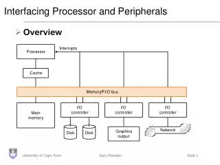
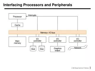
CHAPTER 8 INTERFACING PROCESSORS AND PERIPHERALS. Topics to be covered How to assess I/O system performance Bus functions and types Bus issues such as protocols, bandwidth, and arbitration Interfacing I/O devices to the memory, processor, and operating system I/O performance measures.

E N D
CHAPTER 8INTERFACING PROCESSORS AND PERIPHERALS Topics to be covered • How to assess I/O system performance • Bus functions and types • Bus issues such as protocols, bandwidth, andarbitration • Interfacing I/O devices to the memory, processor,and operating system • I/O performance measures S. Barua – CPSC 440 sbarua@fullerton.edu http://sbarua.ecs.fullerton.edu
I/O Performance Assessment of I/O performance often depends on the Application. If system performance I/O Performance measured by measured by Throughput I/O bandwidth How much data? How many I/O operations? Response time (Elapsed time) I/O latency S. Barua – CPSC 440 sbarua@fullerton.edu http://sbarua.ecs.fullerton.edu
Application System Performance measured by Supercomputer applications Data throughput Single-user machines Response time Commercial and transaction Throughput processing applications & response time S. Barua – CPSC 440 sbarua@fullerton.edu http://sbarua.ecs.fullerton.edu
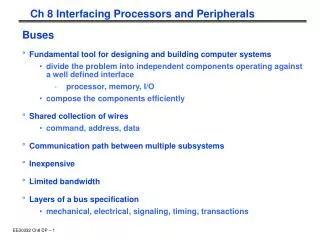
Bus Basics Bus: A shared communication link between the memory and the processor and between the processor and the I/O devices. Three types of buses: • Processor-memory bus • I/O bus • Backplane bus S. Barua – CPSC 440 sbarua@fullerton.edu http://sbarua.ecs.fullerton.edu
Types of Buses Processor-memory bus: Connects processor and memory • Design – specific • Short • Generally high speed • Matched to the memory system so as to maximize memory - processor bandwidth • Requires most hardware S. Barua – CPSC 440 sbarua@fullerton.edu http://sbarua.ecs.fullerton.edu
Types of Buses (Continued) I/O bus • Lengthy • Standardized • Can have many I/O devices connected to them • Often have a wide range in the data bandwidth of the devices connected to them • Requires less hardware • Do not usually interface directly to the memory • Use either a processor-memory or a backplane bus to connect to memory S. Barua – CPSC 440 sbarua@fullerton.edu http://sbarua.ecs.fullerton.edu
Types of Buses (Continued) Backplane bus:Allows processors, memory, and I/O devices to coexist on a single bus • Lengthy • Standardized • Can have many I/O devices connected to them • Requires medium hardware • Balance the demands of processor-memory communication with the demands of I/O device-memory communication S. Barua – CPSC 440 sbarua@fullerton.edu http://sbarua.ecs.fullerton.edu
Communication on the Bus Two basic schemes for communication on the bus • Synchronous & Asynchronous Synchronous Asynchronous Control lines contain clock signal No clock in control lines All devices use same clock Devices have either independent or no clock Devices must be matched Accepts a wide range of devices Easy implementation, little logic More complex logic Faster Slower Must be kept short to maintain speed Can be longer Used for processor-memory bus Used for I/O or backplane bus Protocol based on clock Handshake protocol S. Barua – CPSC 440 sbarua@fullerton.edu http://sbarua.ecs.fullerton.edu
Bus Bandwidth Factors that affect bus bandwidth: • Data bus width Wider bus allows the transfer of multiple words in fewer bus cycles • Separate (not multiplexed) address and data lines Provides faster write operations because address and data can be transmitted in one cycle • Block transfers Sending fewer addresses will reduce the time needed to transfer large block of data S. Barua – CPSC 440 sbarua@fullerton.edu http://sbarua.ecs.fullerton.edu
Bus Access Two techniques available to control bus access: • Single bus master • Processor controls all bus requests • Drawback - Processor must be involved in every bus transaction • Multiple bus masters • Needs bus arbitration (a mechanism for deciding which bus master gets to use the bus next so that the bus is used in a cooperative rather than a chaotic way.) S. Barua – CPSC 440 sbarua@fullerton.edu http://sbarua.ecs.fullerton.edu
Arbitration Schemes for Multiple Masters Bus arbitration steps: • Device wanting to use the bus signals a bus request • After receiving a bus grant, the device can use the bus • Device signals to the arbiter when the bus is no longer needed • Arbiter then grants the bus to another device Two factors considered in deciding which device to grant the bus: • Priority: Device with the highest priority will be serviced first • Fairness:Ensures that every device that wants to use the bus is guaranteed to get it eventually S. Barua – CPSC 440 sbarua@fullerton.edu http://sbarua.ecs.fullerton.edu
Arbitration Schemes for Multiple Masters (Continued) Types bus arbitration schemes : • Daisy chaining (centralized serial arbitration) • Centralized parallel arbitration • Distributed arbitration by self-selection • Distributed arbitration by collision detection (Ethernet) S. Barua – CPSC 440 sbarua@fullerton.edu http://sbarua.ecs.fullerton.edu
Interfacing I/O devices to the Processor and the Memory I/O addressing techniques • Memory -mapped I/O • Isolated I/O (special I/O) I/O transfer techniques • Transfer initiated by the processor Programmed I/O • Transfer initiated by the device Interrupt-driven I/O Direct Memory Access (DMA) S. Barua – CPSC 440 sbarua@fullerton.edu http://sbarua.ecs.fullerton.edu
Direct Memory Access (DMA) For high bandwidth devices such as the hard disks, the transfers consist primarily of relatively large blocks of data. DMA: Allows the data transfer to take place directly between the memory and the I/O by bypassing the processor During DMA operation: • DMA controller becomes the bus master • DMA controller directs the reads or writes between itself and the memory S. Barua – CPSC 440 sbarua@fullerton.edu http://sbarua.ecs.fullerton.edu
DMA (Continued) Steps involved in DMA • Processor sets up the DMA • Processor provides the DMA controller with • address of the device • operation to be performed on the device • memory address • number of bytes to transfer • DMA starts the operation • DMA controller supplies the memory address for read/ write • Transfers the data • Control given back to the processor • Once the DMA transfer is complete, the controller interrupts the processor • Processor regains control over the buses S. Barua – CPSC 440 sbarua@fullerton.edu http://sbarua.ecs.fullerton.edu
I/O Performance Measures • Transaction processing I/O benchmarks • Best known benchmark is the one developed by the Transaction Processing Council (TPC) • Simulates a complex query environment • Measures both I/O rate and data rate • File system benchmarks • SPECSFS – A file server benchmark by SPEC for measuring network file system (NFS) performance • Uses a script of file server requests • Tests the performance of I/O system (both disk & network) and processor • Web I/O benchmarks • SPECWeb – Web server benchmark • Simulates multiple clients requesting both static and dynamic pages from a server • Also simulates clients posting data to the server S. Barua – CPSC 440 sbarua@fullerton.edu http://sbarua.ecs.fullerton.edu