Download
1 / 30
300 likes | 532 Views
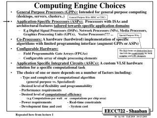
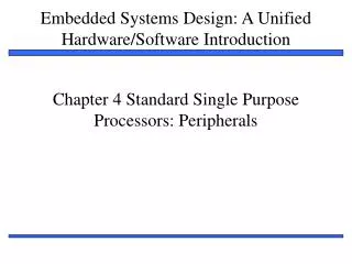
Chapter 4 Standard Single Purpose Processors: Peripherals. Introduction. Single-purpose processors Performs specific computation task Custom single-purpose processors Designed by us for a unique task Standard single-purpose processors “Off-the-shelf” -- pre-designed for a common task

E N D
Introduction • Single-purpose processors • Performs specific computation task • Custom single-purpose processors • Designed by us for a unique task • Standard single-purpose processors • “Off-the-shelf” -- pre-designed for a common task • a.k.a., peripherals • serial transmission • analog/digital conversions
Timers, counters, watchdog timers • Timer: measures time intervals • To generate events at specific times • e.g., hold traffic light green for 10 s • To measure duration between two external events • e.g., measure a car’s speed by calculating time taken by car to pass across 2 separate sensors. • Based on counting clock pulses of known period • E.g., let Clk period be 10 ns • And we count 20,000 Clk pulses • Then 200 microseconds have passed • 16-bit counter would count up to 65,535*10 ns = 655.35 microsec., resolution = 10 ns • Top: indicates top count reached, wrap-around
Basic timer 16-bit up counter Cnt 16 Clk Top Reset • Timer has 16-bit up counter, which increments its value on each clock pulse. • Counter reset to zero. • Output value cnt represents total number of pulse. • To interpret this no. as time interval, we must know the frequency per period of clock signal clk. • Eg: measure time passes between 2 button press. • At first button press, reset the timer and at second button press read the output. • If clock period is 100 MHz, period is (1/100 MHz)=10 nanosec. • If total cnt at second button press is 20,000, so total time elapsed= 20,000*10 nanosec. = 200 microsec. • Resolution minimum interval timer can measure Top value after which timer rolls over to 0
Timer/counter Clk 2x1 mux 16-bit up counter Cnt 16 Top Cnt_in Reset Mode Counters • Counter: like a timer, but counts pulses on a general input signal rather than clock • e.g., count cars passing over a sensor • Can often configure device as either a timer or counter Mode register holds a bit, set by user, to select between Clk input or Cnt_in. If former gets selected, it behaves as timer whereas for latter input, it behaves as counter, counting occurrence of pulse on Cnt_in.
16/32-bit timer 16-bit up counter Clk Cnt1 16 Timer with a terminal count Top1 16-bit up counter Clk Cnt 16 16-bit up counter Cnt2 16 Reset = Top Terminal count Other timer structures • Interval timer • Indicates when desired time interval has passed • We set terminal count to indicate no of clock cycles in the desired interval • Number of clock cycles = Desired time interval / Clock period • Cascaded counters Top2
Time with prescaler Prescaler 16-bit up counter Clk Mode • Prescaler • Divides clock. • Depending on mode bits being given as input to prescaler, prescaler output signal may be same as input signal or it may have half the frequency (double the period), one-forth of frequency, etc. • Increases timer range, decreases resolution • Ex: consider timer resolution= 10ns and range of 65535*10ns= 655.35 microsec. • If prescaler divide the clock frequency by 8, timer resolution = 80ns and range of 65535*80ns= 5.24 millisec.
reaction button indicator light LCD time: 100 ms Example: Reaction Timer • Measure time between turning light on and user pushing button • 16-bit timer, clk period is 83.33 ns, counter increments every 6 cycles • Resolution = 6*83.33=0.5 microsec. • Range = 65535*0.5 microseconds = 32.77 milliseconds • Want program to count 1 millisec., so initialize counter to 65535 – (1X10⁻³ / 0.5X10⁻⁶) = 63535 /* main.c */ #define MS_INIT 63535 void main(void){ int count_milliseconds = 0; configure timer mode set Cnt to MS_INIT wait a random amount of time turn on indicator light start timer while (user has not pushed reaction button){ if(Top) { stop timer set Cnt to MS_INIT start timer reset Top count_milliseconds++; } } turn light off printf(“time: %i ms“, count_milliseconds); }
overflow overflow osc clk to system reset or interrupt prescaler scalereg timereg checkreg Watchdog timer • Must reset timer within every X time unit, else timer generates a signal indicating “time out” . • Common use: reset itself when failure detected; start program from beginning or jump to some safe part of program (ISR). • We might combine both: jump to ISR to test part of system (record no of failures & their cause)and record what went wrong and then reset system. watchdog_reset_routine(){ /* checkreg is set so we can load value into timereg. Zero is loaded into scalereg and 11070 is loaded into timereg */ checkreg = 1 scalereg = 0 timereg = 11070 } void interrupt_service_routine(){ eject card reset screen } /* main.c */ main(){ wait until card inserted call watchdog_reset_routine while(transaction in progress){ if(button pressed){ perform corresponding action call watchdog_reset_routine } /* if watchdog_reset_routine not called every < 2 minutes, interrupt_service_routine is called */ }
Another use: timeouts • ATM machine problem: after entering card, session terminates if at any time the user does not press any button for 2 min. card get ejected and session terminates. • Scalereg: 11 bit up counter; when it overflows, it rolls over to 0. • Timereg: 16 bit up counter, incremented when overflow output from scalereg fed to it. • Checkreg: must be enable to reset watchdog timer. • Once timer is reset, new value can be loaded into timereg and checkreg automatically reset.
What value to load into timereg to achieve timeout of 2 minutes? • Timereg is incremented at every t sec where t= 12 * 211 * 1/(osc frequency) = 12 * 211 * 1/(12 * 106) = 12 * 2048 * (8.33*10-8) = 0.002 sec thus, watchdog timer has resolution of 2 millisec. • Since timereg is a 16-bit register, its range is 0—65535. • Since timereg resolution is 2 millisec, thus timer’s range is (2millisec * 65535)= 131,070 millisec, so to attain the watchdog interval time X millisec, value to be loaded into timereg register timereg value = 2*(216-1)–X = 131070–X For 2 min., X = 120,000 millisec, So timereg= (131070-120,000)= 11,070 i.e. 2B3Eh 11 bit scalereg counter 16 bit timereg counter
embedded device 0 1 1 1 0 1 1 0 Sending UART Receiving UART start bit end bit data 1 0 0 1 1 0 1 1 1 0 0 1 1 0 1 1 Serial Transmission Using UARTs • UART: Universal Asynchronous Receiver Transmitter • Takes parallel data and transmits serially • Receives serial data and converts to parallel • Parity: extra bit for simple error checking • Start bit, stop bit • Baud rate: rate at which bits are send and received. • signal changes per second • bit rate usually higher
Transmitter in UART • The transmitter may possess a register, called as transmit buffer, that holds data to be sent. • Transmit buffer register is a shift register, so that data can be transmitted one bit at a time by shifting at the appropriate rate • After the host processor writes to transmit buffer of the UART, transmitter sends a start bit over its transmit pin (tx), signaling beginning of transmission to remote UART. • Then the transmitter shifts out the data in its transmit buffer over its tx pin at a predetermined rate. • Transmitter also sends additional parity bit, used to determine if received data is correct. • Ex: if no of 1s in the received data add up to an even no, and the parity bit is 1, the data is assumed to be valid else un-valid.
Receiver in UART • The receiver constantly monitors the receive pin (rx) for a start bit. • The start bit is typically signaled by high to low pulse on rx pin. • After the start bit has been detected, the receiver starts sampling the rx pin at predetermined intervals. • Each sampled (received) bit shifted into the receive shift register. • Once data is received, UART signals its host processor. • Host processor in turn reads the byte out of the receive shift register. • Receiver is ready to receive more data now. • If configured, receiver also reads additional bit called parity to determine the authenticity of data.
pwm_o clk 25% duty cycle – average pwm_o is 1.25V pwm_o clk 50% duty cycle – average pwm_o is 2.5V. pwm_o clk 75% duty cycle – average pwm_o is 3.75V. Pulse width modulator • Generates pulses with specific high/low times • Ex: PWM can be used to blink light at specific rate. • Duty cycle: % time high • Square wave: 50% duty cycle • Common use: control average voltage to electric device • Simpler than DC-DC converter or digital-analog converter • Rotation speed (rpm) is proportional to input voltage level.
Suppose 0.01V produces 1 rpm, so to achieve a desired rpm of 125, input voltage is set at 1.25V whereas achieve 250 rpm would require an input voltage of 2.50V • For controlling DC motor, we set the duty cycle to achieve appropriate average voltage. • Now, assuming the PWM output is 5V when high and 0V when low, avg. output= 1.25V when duty cycle= 25%; 5V*25% = 1.25V avg. output= 2.50V when duty cycle= 50%; 5V*50% = 2.50V • Another use: encode commands in single signal for use by another device, receiver uses timer to decode by determining the pulse width • Ex: movement of radio-controlled car can be controlled by sending pulse of different width; 1ms—turn left, 4 ms—turn right, 8 ms—forward.
counter ( 0 – 254) clk_div counter < cycle_high, pwm_o = 1 counter >= cycle_high, pwm_o = 0 clk controls how fast the counter increments 8-bit comparator pwm_o cycle_high Relationship between applied voltage and speed of the DC Motor Internal Structure of PWM 5V DC MOTOR From processor Controlling a DC motor with a PWM Clk_div determine PWM period i.e. no of cycles in the given period (0—254) Cycle_high determine duty cycle i.e. for how many cycles of period should have output 1. The PWM alone cannot drive the DC motor, a possible way to implement a driver is shown below using an MJE3055T NPN transistor. void main(void){ /* controls period */ PWMP = 0xff; /* controls duty cycle */ PWM1 = 0x7f; while(1){}; }
By determining the values of clk_div, we can see that certain frequency is too fast or slow for particular motor. • If value of clk_div is too low (let freq/2, not by freq/8), the value generated by comparator oscillates too quickly, so comparator never outputs zero long enough for DC motor to slow down, causing DC motor to run at full speed. • Setting the value of clk_div to FFh is best suited as only cycle_high is needed to be considered then. • To run motor at 4600 rpm, 50% duty cycle needed. • Value needed to be loaded in cycle_high = 254*0.5= 127= 7Fh • To run motor at 6900 rpm, 75% duty cycle needed. • Value needed to be loaded in cycle_high = 254*0.75= 191= BFh
E communications bus R/W RS DB7–DB0 8 microcontroller LCD controller LCD controller void WriteChar(char c){ RS = 1; /* indicate data being sent */ DATA_BUS = c; /* send data to LCD */ EnableLCD(45); /* toggle the LCD with appropriate delay */ } RS=0, indicate that byte send is control world RS=1, indicate that byte send is data to be displayed Must be toggled each time byte send to LCD
N1 N2 N3 k_pressed N4 M1 M2 M3 M4 4 key_code key_code keypad controller N=4, M=4 Keypad controller
Red A Vd 1 16 Vm White A’ A’ 2 15 B Yellow B A 3 14 B’ Black B’ 4 13 GND GND 5 12 Bias’/Set 6 11 Phase A’ Clk 7 10 CW’/CCW O|C 8 9 Full’/Half Step MC3479P Stepper motor controller • Stepper motor: rotates fixed number of degrees when given a “step” signal • In contrast, DC motor just rotates when power applied, coasts to stop • Rotation achieved by applying specific voltage sequence to coils • Controller greatly simplifies this A unipolar stepper motor has one windings with center tap per phase. Each section of windings is switched on for each direction of magnetic field. In this arrangement a magnetic pole can be reversed without switching the direction of current. Bipolar stepper motors have a single winding per phase. The current in a winding needs to be reversed in order to reverse a magnetic pole.
MC3479P Stepper Motor Driver 8051 CW’/CCW P1.0 P1.1 10 7 B 15 B’ 14 CLK 2 A’ 3 A Stepper Motor The output pins on the stepper motor driver do not provide enough current to drive the stepper motor. To amplify the current, a buffer is needed. One possible implementation of the buffers is pictured to the left. Q1 is an MJE3055T NPN transistor and Q2 is an MJE2955T PNP transistor. A is connected to the 8051 microcontroller and B is connected to the stepper motor. Stepper motor with controller (driver) void main(void){ */turn the motor forward */ cw=0; /* set direction */ clk=0; /* pulse clock */ delay(); clk=1; /*turn the motor backwards */ cw=1; /* set direction */ clk=0; /* pulse clock */ delay(); clk=1; } /* main.c */ sbit clk=P1^1; sbit cw=P1^0; void delay(void){ int i, j; for (i=0; i<1000; i++) for ( j=0; j<50; j++) i = i + 0; }
8051 P2.4 P2.3 P2.2 P2.1 P2.0 GND/ +V Stepper Motor +V 1K Q1 +V B 1K A Q2 330 Stepper motor without controller (driver) /*main.c*/ sbit notA=P2^0; sbit isA=P2^1; sbit notB=P2^2; sbit isB=P2^3; sbit dir=P2^4; void delay(){ int a, b; for(a=0; a<5000; a++) for(b=0; b<10000; b++) a=a+0; } void move(int dir, int steps) { int y, z; /* clockwise movement */ if(dir == 1){ for(y=0; y<=steps; y++){ for(z=0; z<=19; z+4){ isA=lookup[z]; isB=lookup[z+1]; notA=lookup[z+2]; notB=lookup[z+3]; delay(); } } } /* counter clockwise movement */ if(dir==0){ for(y=0; y<=step; y++){ for(z=19; z>=0; z - 4){ isA=lookup[z]; isB=lookup[z-1]; notA=lookup[z -2]; notB=lookup[z-3]; delay( ); } } } } void main( ){ int z; int lookup[20] = { 1, 1, 0, 0, 0, 1, 1, 0, 0, 0, 1, 1, 1, 0, 0, 1, 1, 1, 0, 0 }; while(1){ /*move forward, 15 degrees (2 steps) */ move(1, 2); /* move backwards, 7.5 degrees (1step)*/ move(0, 1); } } A possible way to implement the buffers is located below. The 8051 alone cannot drive the stepper motor, so several transistors were added to increase the current going to the stepper motor. Q1 are MJE3055T NPN transistors and Q3 is an MJE2955T PNP transistor. A is connected to the 8051 microcontroller and B is connected to the stepper motor.
Analog-to-Digital Convertor • We can compute the digital values from the analog values, and vice-versa, using the following ratio: • Vmax is the maximum voltage that the analog signal can assume, n is the number of bits available for the digital encoding, d is the present digital encoding, and e is the present analog voltage.
Vmax = 7.5V 4 4 1111 7.0V 1110 6.5V 1101 3 3 6.0V 1100 5.5V 1011 2 2 analog input (V) analog output (V) 5.0V 1010 4.5V 1001 1 1 4.0V 1000 3.5V 0111 time time 0110 3.0V t1 t2 t3 t4 t1 t2 t3 t4 2.5V 0101 0100 1000 0110 0101 0100 1000 0110 0101 2.0V 0100 Digital input Digital output 1.5V 0011 1.0V 0010 0.5V 0001 0V 0000 analog to digital digital to analog proportionality Analog-to-digital converters SupposeVmax is 7.5V. Then for e= 5V, we have the following ratio: e / Vmax= d / (2n-1) = 5/7.5 = d/15, resulting in d = 10D = 1010B, as shown in Figure. The resolution of a DAC or ADC is defined as Vmax/(2n-1), representing the number of volts between successive digital encodings. Here, it is 0.5V.
A DAC has n inputs for the digital encoding d, a Vmax analog input, and an analog output e. A fairly straightforward circuit (involving resistors and an op-amp) can be used to convert d to e. • ADCs, on the other hand, require designs that are more complex, for the following reason. • Given a Vmax analog input and an analog input e, how does the converter know what binary value to assign in order to satisfy the above ratio? Unlike DACs, there is no simple analog circuit to compute d from e. • Instead, an ADC may itself contain a DAC also connected to Vmax. The ADC "guesses" an encoding d, and then evaluates its guess by inputting d into the DAC, and comparing the generated analog output e’ with the original analog input e (using an analog comparator). • If the two sufficiently match, then the ADC has found a proper encoding.
So now the question remains: how do we guess the correct encoding? • A faster solution uses what programmers call binary search, or "successive approximation" in analog-digital terminology. • We start with an encoding corresponding half of the maximum value, resulting in analog value. • We then compare the resulting analog value with the original (value to be converted); if the resulting analog value is greater (less) than the original, we set the new encoding to halfway between this one and the minimum (maximum). • We continue this process, dividing the possible encoding range in half at each step, until the compared voltages are equal. • This technique requires at most n comparisons. However, it requires a more complex converter.
Because ADCs must guess the correct encoding, they require some time. • Thus, in addition to the analog input and digital output, they include an input "start" that starts the conversion, and an output "done" to indicate that the conversion is complete.
0 0 0 0 0 0 0 0 0 1 0 1 0 0 0 0 0 1 0 0 0 0 0 0 0 1 0 1 0 1 0 0 0 1 0 0 0 0 0 0 0 1 0 1 0 1 0 0 0 1 0 1 0 0 0 0 0 1 0 1 0 1 0 1 Digital-to-analog conversion using successive approximation Given an analog input signal whose voltage should range from 0 to 15 volts, and an 8-bit digital encoding, calculate the correct encoding for 5 volts. Then trace the successive-approximation approach to find the correct encoding. 5/15 = d/(28-1) d= 85 Encoding: 01010101 Successive-approximation method ½(Vmax + Vmin) = 7.5 volts Vmax = 7.5 volts. ½(5.63 + 4.69) = 5.16 volts Vmax = 5.16 volts. ½(7.5 + 0) = 3.75 volts Vmin = 3.75 volts. ½(5.16 + 4.69) = 4.93 volts Vmin = 4.93 volts. ½(7.5 + 3.75) = 5.63 volts Vmax = 5.63 volts ½(5.16 + 4.93) = 5.05 volts Vmax = 5.05 volts. ½(5.63 + 3.75) = 4.69 volts Vmin = 4.69 volts. ½(5.05 + 4.93) = 4.99 volts