Download
1 / 22
230 likes | 245 Views
Reaction Turbines. Reaction Turbines. A reaction turbine is a pressure turbine i.e. the water enters the wheel under pressure after passing through the guide vanes.

E N D
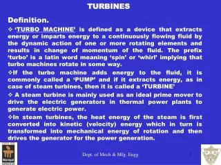
Reaction Turbines • A reaction turbine is a pressure turbine i.e. the water enters the wheel under pressure after passing through the guide vanes. • At the outlet of turbine, the pressure is atmospheric or below atmospheric if the discharge is taken through a draft tube into the tail race. Owing to this difference of pressure, the water flows through the vanes of the turbine towards the outlet. Thus difference of pressures exist throughout the runner.
Reaction Turbines • The difference of pressure between guide vanes and the runner, called reaction pressure, is responsible for the motion of the runner. Therefore, such a turbine is also called a reaction turbine. • As the water passes through the vanes, pressure energy is continuously converted into the velocity energy which is transferred to the wheel and it rotates. • Finally, water is discharged into the tailrace through the draft tube, which is a closed tube of enlarging cross section, the other end of which is submerged in the tailrace.
Evaluation of Reaction Turbines • The power produced by a turbine is proportional to QH. If the demands permits, we would like to produce as much as possible from a unit. If the water is available in abundance at high altitudes, obviously we can produce as much power as desired. The design criteria will only be limited by mechanical considerations of the turbine i.e. material, space etc and not by hydraulic considerations.
Evaluation of Reaction Turbines • But is it possible to increase Q to any extent in a turbine to get high power? • In case of Pelton turbines, it is observed that the impulse wheel gives best performance or highest efficiency when its speed ratio is approximately 0.46 i.e
Evaluation of Reaction Turbines • This means, for low heads H, either D or N has to be reduced to maintain this constant speed ratio. But N, speed of the runner, cannot be decreased as the turbines are to be coupled with high speed electric generators. Thus, diameter of the runner D has to be reduced. With limited size of the runner, discharge through the nozzle will also be limited. Hence, Pelton turbines become unsuitable for low heads.
Evaluation of Reaction Turbines • This limitation of Pelton or impulse turbines led to the investigations of some other type of turbines. As a result, reaction turbine came into existence in which water is admitted all around the turbine runner under pressure and turbine functions under a difference of pressure between the inlet and the outlet. For such a type of turbine, it has been found that speed ratio can be increased safely to a higher value to have larger wheels that will admit high flow to pass through them.
Francis Turbine • A Francis turbine is a mixed flow turbine in which the water enters at the circumference of the runner and travels towards the axis of the runner. Finally, it comes out axially along the shaft. • It operates under medium heads and requires medium quantity of flow. • The water through the guide vanes and then through runner vanes, transferring its energy to the runner. • Finally, the water is discharged into the tailrace through a draft tube.
Main components A Francis turbine has the following main components • Penstock • Scroll Casing • Guide Mechanism • Runner and runner vanes • Draft tube
Penstock • It is the waterway used to carry the water from the reservoir to the turbine. At the inlet of the penstock, trashracks are used to prevent the debris from going into the turbine.
Scroll Casing • It is the casing around the turbine wheel and it evenly distributes the water around the circumference of the wheel. It is also called spiral casing. • Cross section gradually decreases to maintain velocity and pressure, maximum at the entrance to zero at the tip. • Usually made of steel or concrete and is water tight
Guide Mechanism • It has a guide wheel consisting of guide vanes. The guide vanes are to facilitate smooth and eddiless flow. Each guide vane can be moved on its pivot centre, thus changing the area of flow into the runner. This regulates the flow to meet the varying requirements of demand. • Material for the guide vanes is usually cast steel.
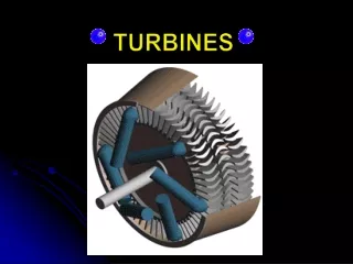
Runner and Runner Vanes • Runner is a circular wheel having radial vanes (radial curved) installed on it • Runner vanes have a smooth surface and are shaped to ensure that water enters and leaves without shock • Made of iron or stainless steel and are keyed to the shaft
Draft Tube • Water flows from the runner to the tail race through a tube called draft tube • Usually diverging in cross section and is fully airtight • Takes water from the runner to the tail race
Example-1: What will be the increase in power and efficiency of a reaction turbine producing 500 kW, under a head of 6m and a discharge of 10 m3/s, if its draft tube of cylindrical cross section of diameter 1.75m is replaced by a tapered one having an outlet diameter of 2m. Assume efficiency of the draft tube 92%. Solution: H = 6 m P = 500 kW Q = 10 m3/s ηd = 0.92 Do = 1.75 m Dd = 2 m