Download
1 / 53
530 likes | 730 Views
Basic Detection Techniques Front-end Detectors for the Submm. Andrey Baryshev /Wolfgang Wild Lecture on 10 Oct 2011. Contents overview. Submm / THz regime Definition and significance Science examples Submm detection: direct + heterodyne Heterodyne receiver systems

E N D
Basic Detection TechniquesFront-end Detectors for the Submm AndreyBaryshev/Wolfgang Wild Lecture on 10 Oct 2011
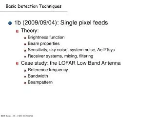
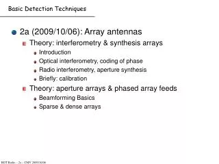
Contents overview • Submm / THz regime • Definition and significance • Science examples • Submm detection: direct + heterodyne • Heterodyne receiver systems • Signal chain, block diagram • Heterodyne principle • Noise temperature and sensitivity • Heterodyne frontend • Mixers • Local oscillators • IF amplifiers • Spectrometers: Filterbank, AOS, Autocorrelator, FFT • Overview submm astronomy facilities • Examples of heterodyne receiver systems • ALMA 650 GHz • HIFI space instrument • Direct detection systems • Signal chain, block diagram • Types of direct detectors and operating principles • Noise equivalent power (NEP) • Examples of a direct detection system • Quasi optics Practical work at SRON Measurement of sensitivity of heterodyne and direct detection system. Basic Detection Techniques – Submm receivers
Submillimeter/THz Wavelength Regime I • λ ~ 0.1 … 1 mm • Photon energy corresponds 2-20 K in temperature scale(hF =kT) • Between infrared/optical and radio waves • Submm technology is relatively new (~ 20 years) (Compare to optical technology: ~ 400 years) • Submm astronomy is crucial for understanding star and planet formation • Range of 0.1… 0.3 mm is one of the last unexplored regimes in astronomy Basic Detection Techniques – Submm receivers
Submillimeter Wavelength Regime II • Technically challenging and interesting • Challenging: small λ means high precision fabrication • Interesting: Combination of optical and electronic techniques • Submm astronomy and technology are very dynamic fields Basic Detection Techniques – Submm receivers
Advantages of THz radiation • Definition • Frequency range 0.5 - 6 THz • Emerging field (largely unexplored) • Unique properties • Many spectral features in THz region • See through many materials • Sensitive to water • Presently used for astronomy, Earth observation Water, gas Image of a galaxy Image made by A. Baryshev Spectrum of ethanol and water Image made by A.Baryshev THz radar image THz image Basic Detection Techniques – Submm receivers
Why submillimeter ?Sub-/Millimeter vs. optical astronomy Sub-/Millimeter astronomy studies the Cold Universe. And most of the sky is dark and cold … Basic Detection Techniques – Submm receivers
Radiation at (sub)mm wavelengths • Continuum: cold dust at 10-100 K (black body of 30K peaks at 0.1 mm) • Lines: pure rotational transitions of molecules Sub-/mm radiation probes cold molecular clouds of gas and dust Energy levels of CO and CS Basic Detection Techniques – Submm receivers
The Earth atmosphere at submm wavelenghts • The Earth atmosphere is only partially transparent for submillimeter wave radiation • Several atmospheric “windows” exist • Water vapor and oxygen cause strong absorption dry, high observatory sites airplane, balloon and space platforms Basic Detection Techniques – Submm receivers
Atmospheric transmission at 5000m altitude pwv = precipitable water vapour, i.e. the column height of condensed water vapour Basic Detection Techniques – Submm receivers
Submillimeter astronomy – star formation • New stars form in molecular clouds • These clouds are best observed in the infrared and submm regime since they are cold and have high optical extinction • Star and planet formation is associated with a rich interstellar chemistry many lines observable in IR/submm/mm JCMTSpectral SurveyIRAS16293- 2422 Basic Detection Techniques – Submm receivers
Cazaux et al. 2003 Basic Detection Techniques – Submm receivers
Orion Trapezium Region at Optical Wavelengths Highlighted Region at IR Optical vs. Submm/Far-Infrared Basic Detection Techniques – Submm receivers
Molecular gas in M31 CO line emission traces molecular gas. This is where new stars form. Nieten et al. 2005 Basic Detection Techniques – Submm receivers
Comet water HDO/H2O ratio measured by Herschel Space Observatory in THz Water in comets is the same as on Earth Basic Detection Techniques – Submm receivers
Dust and CO at z=6.4 ! Sloan survey: optical image Contours: dust Z=6.4 => Heavy elements formed shortly after Big Bang IRAM 30m MAMBO Bertoldi et al. 2003 Basic Detection Techniques – Submm receivers
Two Main Detection Schemes for Sub-/mm Radiation • Incoherent detection direct detectors (bolometer) • total power detection • no phase information used on single antenna • low spectral resolution • Coherent detection heterodyne receiver • frequency down conversion • high spectral resolution • phase information single antenna and interferometer Heterodyne technique and receivers will be treated here. Design of a Scientific Instrument
Heterodyne Signal Chain electrical Intermediate Frequency (IF) Spectrometer/ Correlator Heterodyne Instrument Data acquisition optical “Front End” “Backend” • Convert incoming radiation into electronic signal (IF) for further processing • Spectral information is preserved (spectral resolution Δf/f determined • by backend) • Heterodyne detection achieves spectral resolution > 106 Design of a Scientific Instrument
Principle of Heterodyne Mixing Heterodyne principle = mixing of two frequencies (signal + local oscillator) to produce (sum and) difference signal (intermediate frequency = IF) Mixing needs non-linear element (e.g. diode, SIS junction) = mixer f IF = | f LO - f RF | Double sideband mixer: both sidebands converted to same IF Single sideband mixer: Only one sideband converted to IF Sideband separating mixer: two sidebands converted to different IF outputs LO IF RF RF // freq 0 fIF Lower sideband (LSB) Upper sideband (USB) Design of a Scientific Instrument
Heterodyne Mixing Combine strong LO signalVLO= cos(LOt) (e.g. 996 GHz) + A weak RF signalVS= cos(St+) (e.g. 1002 GHz) Gives total power absorbedP ~ VSVLOcos((S -LO)t +)+…. Amplitude and phase information conserved in IF signal Detect radiation at frequencies where no amplifiers are available IF signal Local Oscillator 996 Mixing needs strong non-linear detector charcteristic Design of a Scientific Instrument
Block Diagram of a Heterodyne Receiver LO signal (e.g. 646 GHz) IF signal out (e.g. 4 GHz) LO ref in Local oscillator to correlator or spectrometer Cal source Optics Mixer IF amp(s) 4 K Astronomical RF signal (e.g. 650 GHz) • Components: Optics • Mixer • Local Oscillator (LO) • Calibration source • IF amplifier(s) • Dewar and cryogenics • Bias electronics • Spectrometer(s) Design of a Scientific Instrument
A Heterodyne Receiver Design of a Scientific Instrument
A heterodyne receiver for space Telescope Beam HIFI = Heterodyne Instrument for the Far-Infrared Will fly on the Herschel Space Observatory in 2008 7 LO Beams ~ 50 cm Design of a Scientific Instrument
Local Oscillator Unit Telescope LOU optics Focal Plane Unit mixer IF IF spectrometers LSU HRS WBS ICU Instrument Control Unit Local Oscillator Source Unit To Astronomer HIFI Signal Path Design of a Scientific Instrument
Main components of a heterodyne front-end • Optics last part of this college • Submillimeter wave mixer • SIS = Superconductor-Insulator-Superconductor • HEB = Hot-Electron-Bolometer • (Schottky = Semiconductor-metal contact diode) • Local Oscillator • Multiplier chain • Quantum-Cascade-Laser (QCL) • Intermediate frequency (IF) amplifiers Basic Detection Techniques – Submm receivers
Sensitivity and Noise Temperature • In radio and submm astronomy, the signal unit “Temperature” is used. • This is really a signal power W = k T Δν (k Boltzman constant) • Usually the signal power is much smaller than the noise power (“noise temperature”) of the receiving system. • The noise temperature of a system is defined as the physical temperature of a resistor producing the same noise power. • Difference measurements are used to detect the signal, e.g. (sky + signal source) minus (sky) Basic Detection Techniques – Submm receivers
The “ideal” submillimeter wave receiver Converts all incoming radiation into an electric signal no photons “lost” has no own noise contribution However: Heisenberg’s uncertainty principle (ΔE x Δt ≥ h/2π) makes such a noiseless mixer impossible. Why ? – A heterodyne mixer measures signal amplitude andphase. This corresponds to number of photons and time in the photon picture which – according to the uncertainty principle – cannot be measured simultaneously with infinite precision. This uncertainty results in a minimum noise of a heterodyne mixer, the “quantum limit”. Current best mixers are ~few times worse than the quantum limit. Basic Detection Techniques – Submm receivers
Sensitivity of a receiving system Question: What is the smallest detectable signal ? The answer is the Radiometer formula (Sensitivity): Tmin = c1 Tsys / (t )1/2 Received noise power from an antenna / receiver system: Noise power Wsys = WA + Wrx = k Tsys = k (TA + Trx ) Tsys = TA + Trx system bandwidth system temperature integration time receiver noise temperature antenna temperature (signal, atmosphere, antenna losses) Basic Detection Techniques – Submm receivers
Noise Contributions from Receiver Components Question: What is the noise contribution from different receiver components ? Receiver as a series of linear two-ports: T: noise temp G: Gain Optics Mixer 1st IF amplifier To detector T1, G1 T2, G2 T3, G3 Tn, Gn Trx = T1 + T2 / G1 + T3 / (G1 G2 ) + … + Tn / ( G1 G2 …. Gn ) Receiver noise temperature determined by first few elements Cooled optics for high frequencies Basic Detection Techniques – Submm receivers
HIFI signal chain Basic Detection Techniques – Submm receivers
Sub-/millimeter Optics • Main function: coupling of the antenna signal into mixer • Used components: • Lenses (e.g. PTFE, quartz) • Mirrors (plane and focusing) • Feed horn • Grids (polarization separation) • quarter / half-wave plates • Martin-Puplett Interferometers • Gaussian optics used in sub-/mm regime (separate lecture) Basic Detection Techniques – Submm receivers
Cryogenic submillimeter mixers SIS = Superconductor-Insulator-Superconductor - used in mm and submm from ~70 GHz to ~1200 GHz - very good performance - theory well understood - submm detector of choice at ground-based and space telescopes HEB = Hot-Electron-Bolometer - used above ~1200 GHz into THz regime - performance better than SIS above 1200 GHz - theory not well understood - active research on-going Basic Detection Techniques – Submm receivers
S I S The SIS mixer The SIS mixer (Superconductor-Insulator-Superconductor) element is a sandwich structure with a very thin insulator. Superconductor-Insulator-Superconductor (SIS) Tunnel Junctions Cross section of a typical Niobium SIS tunnel junction • insulator thickness <= 1nm : tunneling SEM view of junction top electrode (1x1 µm²) Basic Detection Techniques – Submm receivers
Bandgap structure of an SIS mixer Energy gap Din density of states: no current below Vbias = 2D/e low shot noise root singularity in density of states: large current flow at VGap extremely sharp nonlinearity „Semiconductor“ model for SIS„Quasiparticle Excitations“ ~ Electrons Superconductor 1at V ~ VGap Superconductor 2grounded Ins. (Cooper pair tunneling effects not shown !) Basic Detection Techniques – Submm receivers
SIS mixer principle = photon assisted tunneling Photon assisted tunneling (Dayem&Martin) series of steps at V = UGap – nhn/e Frequency limit for mixing at hn = 4D (1400 GHz for Nb) LO power: PLO ~ (hn/e)²/RN (800 GHz, 20 Ohms: 0.5µW) Basic Detection Techniques – Submm receivers
Some formulas Basic Detection Techniques – Submm receivers
300, 400, 800 GHz photon steps Basic Detection Techniques – Submm receivers
Different RF power Load line Basic Detection Techniques – Submm receivers
Typical SIS mixer responce Basic Detection Techniques – Submm receivers
SIS mixer implementation Task: Couple the astronomical signal to the (very small, ~1 μm2) tunnel junction. Two ways are used: • Feedhorn and waveguide (waveguide mixer) or • A lens and antenna structure (quasi-optical mixer) Basic Detection Techniques – Submm receivers
Example of a waveguide SIS mixer (540-700 GHz) 10 mm Junction holder Lens Feed horn Magnet Basic Detection Techniques – Submm receivers
Precision machining 0.1 mm Human hair Backshort cavity Mixer backpiece Terahertz mixer With SIS chip and tunnel junction Basic Detection Techniques – Submm receivers
HIFI mixers 800-960 GHz and 960-1120 GHz These mixers fly now on the Herschel Space Observatory Basic Detection Techniques – Submm receivers
HIFI mixer design magnet Pressure unit IF-board Re-alignment spring Magnet pole shoes Device mount with backshort, substrate channel and alignment spring ESD protection, bias and LF filtering Corrugated horn Cover for bias/ESD PCB Basic Detection Techniques – Submm receivers
Example of a quasioptical mixer structure 10 mm 0,25 mm Antenna structure SIS junction Stripline Mixer chip Lens Basic Detection Techniques – Submm receivers
Quasi-optical mixer implementation Quasi-optical mixer for the Space instrument HIFI Chalmers Technical University Gothenburg, Sweden 1.5 THz Silicon lens IF board Main challenges: - chip alignment on lens - optical properties, beam direction Basic Detection Techniques – Submm receivers
Hot electron bolometer (HEB) principle Thin superconducting film Square law power detector thermal time constant t = C/GC: thermal capacitanceG: thermal conductivity Mixer operation: can detect beat frequency between LO and signal has to be very fast (ps) for few GHz IF(needed for spectroscopy) Basic Detection Techniques – Submm receivers