Download
1 / 32
320 likes | 527 Views
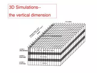
DUNE Condensation Prevention 3D Simulations with Duct Fans. Erik Voirin April 29, 2019. 3D model update. Previous 2D model had Duct(s) running along length of cryostat We wanted to update this to a full 3D model and include realistic ventilation return locations.

E N D
DUNE Condensation Prevention3D Simulations with Duct Fans Erik Voirin April 29, 2019
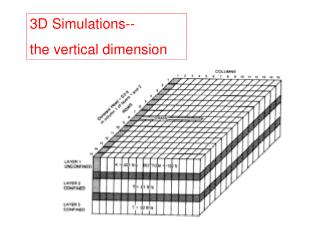
3D model update • Previous 2D model had Duct(s) running along length of cryostat • We wanted to update this to a full 3D model and include realistic ventilation return locations. • Tried Several Configurations starting with the most simple (no additional work or equipment), most of which showed cryostat surface temperature below dewpoint (48F) • Two Configurations worked (all surfaces above dewpoint) 1.) 4 exit locations (1 in each bottom corner) and Heaters underneath cryostat 2.) 1 Exit location with Ducts and Duct fans underneath Cryostat E. Voirin| DUNE Condensation Prevention
Ventilation Inlet Temperature = 67.91F (In order to have an average air temperature of 67F in the upper cavern per the minimum temperature spec.) E. Voirin| DUNE Condensation Prevention
Boundary Conditions: • 15000 SCFM Air flow in Top Cavern • 67.9F Inlet Temperature • Target 67F average Temperature in Top Cavern • Radiation Model: (Single band grey surface emissivity) • Discrete Transfer Surface to Surface (Transparent gas) • Emissivity Concrete and Painted steel girders: • 0.7 used in model (References say 0.8-0.9) • Emissivity of Cryostat Outer Wall: • 0.34 for bottom and sides (SS plate reference) • 0.7 for Top (If we paint the top, References say 0.9 for paint) • Constant Air Properties: 1atm and 60oF (RefProp v9.1) • Boussinesq Buoyancy model: Beta = 0.0034741 K-1 • 88K on Inside of 0.8m thick insulation: 29.6 kW Cooling Load. E. Voirin| DUNE Condensation Prevention
Only 1 Ventilation Exit in 1 corner. (+X, +Z)Frost on Cryostat Bottom, condensation on sides E. Voirin| DUNE Condensation Prevention
2 Exits (one on each end on Positive X side)No Heaters. Condensation on Bottom E. Voirin| DUNE Condensation Prevention
4 Exits (One in each corner) E. Voirin| DUNE Condensation Prevention
Add Heaters along Cryostat Bottom2 lines of heaters routed through the openings in the bottom of the cryostat: (14.53 Watts per foot) (5800 Watts Total) E. Voirin| DUNE Condensation Prevention
Channel Near Center E. Voirin| DUNE Condensation Prevention
Ducts Underneath Cryostat with Duct Fans @ End • Two 24” Cylindrical Ducts running along the length of the cryostat. • Several specific sized holes in them along the length to balance flow. • Open ends on Far End. • Details of openings sizes explained later • Rectangles cut into ducts on both sides, same height, varying lengths. • Duct Fans Exhaust into open space between cryostats near Ventilation Exit. • Total Enthalpy (Temperature) conserved from Duct Inlets to fan exhaust. • No additional Heat from fan added • (~4 kW) = 0.9F Temperature change E. Voirin| DUNE Condensation Prevention
Simulation #1: 7000 SCFM Flow from each Duct Fan • 1000 SCFM from End • 1000 SCFM from each set of Duct holes along length. • Ducts Run through these 0.8m openings which travel the length of the cryostat E. Voirin| DUNE Condensation Prevention
Duct Hole Sizes and Flow Balancing (23.9” Inner diameter used in simulations) Flow balancing with 6000, 7000, and 8000 SCFM Flow: Flow Stays Balanced even with variable fan flow rates. So the same hole sizes will work regardless of actual fan flow rates. Hole Areas: We can vary the aspect ratio of the holes if it is easier to cut holes differently. DUCT MUST BE AIR TIGHT OTHER THAN THE ENGINEERED HOLES! E. Voirin| DUNE Condensation Prevention
Fan Curve, Duct Static Pressure, andDuct Total Pressure Curves E. Voirin| DUNE Condensation Prevention
Surface Temperature: Above 48F Dew Point Everywhere.Coldest area on Bottom of Cryostat (7000 SCFM per Duct) E. Voirin| DUNE Condensation Prevention
Surface Temperature: Above 48F Dew Point Everywhere.Coldest area on Bottom of Cryostat (6000 SCFM per Duct) Duct Flow Sensitivity: (0.7 degree difference from 7000 SCFM) 5% of total Delta T change from a 17% change in Flow E. Voirin| DUNE Condensation Prevention
Air Flow between cryostat and wall (Side with Ventilation Exit) (7000 SCFM per Duct) E. Voirin| DUNE Condensation Prevention
Air Temperature between cryostat and wall (Side with Ventilation Exit) (Concrete Temp shown as well) (7000 SCFM per Duct) E. Voirin| DUNE Condensation Prevention
Air Temperature between cryostat and wall (Side with Ventilation Exit) (Concrete Temp shown as well) (6000 SCFM per Duct) E. Voirin| DUNE Condensation Prevention
Air Flow between cryostat and wall (Opposite Side of Ventilation Exit) (7000 SCFM per Duct) E. Voirin| DUNE Condensation Prevention
Air Flow between cryostat and wall (Opposite Side of Ventilation Exit) (6000 SCFM per Duct) E. Voirin| DUNE Condensation Prevention
Air Temperature between cryostat and wall (Opposite Side of Ventilation Exit) (Concrete Temp shown as well) (7000 SCFM per Duct) E. Voirin| DUNE Condensation Prevention
Air Temperature between cryostat and wall (Opposite Side of Ventilation Exit) (Concrete Temp shown as well) (6000 SCFM per Duct) E. Voirin| DUNE Condensation Prevention
Center Plane Air Temperature (7000 SCFM per Duct) E. Voirin| DUNE Condensation Prevention
Center Plane Air Temperature (6000 SCFM per Duct) E. Voirin| DUNE Condensation Prevention
Possible Duct Fan:https://www.cincinnatifan.com/catalogs/Tube-Axial-internet.pdf • WAFX23.50-8HD @ 2333 RPM • Other fans will work as well depending on their fan curve. • Duct and Fan Will be mounted to floor to prevent vibrations from transferring to cryostat. • Electrical Isolation from cryostat as well E. Voirin| DUNE Condensation Prevention
Duct Centerline Static And Total Relative Pressure with 8000 SCFM Flow per duct. E. Voirin| DUNE Condensation Prevention
Relative Static Pressure on Center Plane through set of holes closest to Fan (8000 SCFM Flow Through Duct, 1143 SCFM through this set of holes) E. Voirin| DUNE Condensation Prevention
Velocity Vectors on Center Plane through set of holes closest to Fan (8000 SCFM Flow Through Duct, 1143 SCFM through this set of holes) E. Voirin| DUNE Condensation Prevention
Equipment Failure Scenarios: 1 Duct Fan inoperable, other running @ 7000 SCFM Still Above 48F Dew Point with 1 Fan Failure E. Voirin| DUNE Condensation Prevention
No Fans Running, No Ventilation, Transient Cooling down to condensation • 88.4 hours until Surface Temperature reaches 48F • Small blip in Air Temperature @ ~13 hours is updating the fluid velocity field, which changes the convection coefficients slightly. E. Voirin| DUNE Condensation Prevention
Initial Temperature/Velocity of Representative Geometry(7000 SCFM Initial Duct Fan Flow to 2 Fans) E. Voirin| DUNE Condensation Prevention
Final Temperature/Velocity of Representative Geometry (88.4 hours after all ventilation stops) E. Voirin| DUNE Condensation Prevention