Download
1 / 30
310 likes | 621 Views
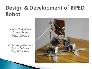
Introduction to Biped Walking. Lecture 1 Background, simple dynamics, and control. Some Sample Videos. Human Walk.avi Hubo straight leg.avi. Human Leg Anatomy. Torso. Hip, 3DOF. Knee, 1DOF. Ankle, 2DOF. Toes, ~2 DOF. Building Blocks of Biped Walking. Dynamic modeling

E N D
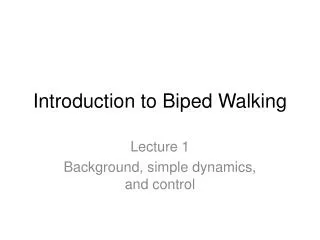
Introduction to Biped Walking Lecture 1 Background, simple dynamics, and control
Some Sample Videos • Human Walk.avi • Hubo straight leg.avi
Human Leg Anatomy Torso Hip, 3DOF Knee, 1DOF Ankle, 2DOF Toes, ~2 DOF
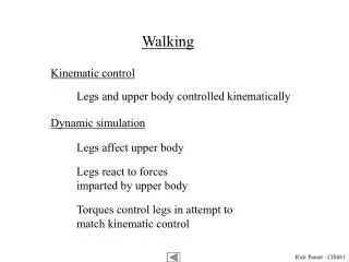
Building Blocks of Biped Walking • Dynamic modeling • Trajectory generation • Inverse kinematic model • Trajectory error controllers • Additional failure mode controllers • Mechatronics • Programming • Provides virtual experimentation platform • The ideal path that the hips and feet follow. • Specifies the joint movements to make feet and hips follow the trajectory • Specify how the joints should move to compensate for trajectory error. • Adjusts the trajectory to compensate for nonidealities. • The structure and implementation and the limitations thereof • Reading sensors, processing and filtering their data, sending joint position commands.
Walking Cycle (2D) Kim, Jung-Yup (2006)
Stages Kim, Jung-Yup (2006)
Controllers • Damping Controller reduces reactive oscillations to swinging legs • ZMP controller minimizes ankle torque and optimizes hip trajectory • Landing controller limits impact forces at foot, controls foot angle • Torso/pelvis controllers follow prescribed trajectory • Tilt-over controller adjusts foot placement if ZMP becomes unstable • Landing position controller adjusts foot landing to compensate for excess angular velocity Kim, Jung-Yup (2006)
Block Diagram of KHR-2 Kim, Jung-Yup (2006)
Balance Control • Controls Center of mass location • Prevents tiltover • Controls foot placement during landings • Consists of: • Torso sway damping controller • ZMP controller • Foot placement controller • Foot Landing Controller
Single Support Vibration Modeling • Compliance between ankle and torso • Model robot body as lumped mass • Model flexible parts and joints as spring • Use Torque along X axis of ankle to counteract motion • Linearize with small angle
Vibration Damping Control • Apply Laplace Transform • Factor out Θ(s) and U(s) to form transfer function • Substitute to find TF of Torque wrt input angle
Damping Controller • Substitute β= K/ml2−g/l α=K/ml2 • Apply derivative feedback of error • Simulation shows effect of damping on vibrations • (See )“vibdamp.mdl”
Joint Motor Controller Basics • DC brush motors • Harmonic drive gear reduction • Simple governing equations • Inefficient at low speeds
Joint Motor Controller Motor Voltage/Speed constant (V-s/rad) Rotor Inductance (Henry) Rotor Resistance (Ω) Input Voltage (V) Current (Amp) Output Torque (N-m) Motor equivalent viscous friction (N-m-s) Block Diagram of System
Effects of Motor on Control • Torque limit due to R • torque inversely proportional to speed • High current (and heat) at zero speed
Ankle model with motor • Assume simple inverted pendulum • Combine electrical and mechancal ODE’s
Point about which sum of inertia and gravitational forces = 0 Requires no applied moment to attain instantaneous equilibrium Control objective: minimize horizontal distance between COM and ZMP Zero Moment Point
Divide ZMP control into 2 planes Track hip center to ZMP Requires dynamic model or experiment to determine model parameters Pole placement compensator (See “ZMP.mdl”) Single Support Model Kim, Jung-Yup (2006) Double inverted pendulum
Foot Landing Placement • IMU measures X and Y angular velocity • Hip sway monitored by trajectory controllers • Excess angular velocity reduced by widening landing stance • Reduced angular velocity maintains hip trajectory Kim, Jung-Yup (2006)
Landing Problem • Foot landing causes impact and shock to system • Dynamics of shock are difficult to model • Large reaction forces • Angular momentum controlled with 1 ankle Before After v2 v’2 v1 v’1=0 M(t) Fz(t)
Simplified Collision Dynamics • Governing Formulas • Impact Energy Losses • Power Input Impact Before After v2 v1
Deriving the ideal model mT • Ideal mass-spring-damper • mT≈53kg (hubo’s mass) • c, k = model constants • Form transfer function • Solve numerically
Dynamic Model of knee mT • Lump mass of torso at hip • Lagrange method to derive dynamics • Add artificial damping to reduce simulation noise • Use PID control to stabilize
Knee Inverse Kinematics • Need to solve θi(x,t) (i=1,2) • Desired path along y axis (x=0) • Setup constraint equations & solve • Apply as input to model
Trajectory Generation “Goal” Control Trajectory Feedforward Requires mathematical model Input conditioned for system Requires online computation Allows path optimization • Needs no knowledge of model • Low computation overhead • Non-optimal path
Hubo’s Hip Trajectory • Y=A*sin(ωt) • A=sway amplitude • Ω= stride frequency (rad/s) • Simplifies frequency domain design • X=c*A1cos(ωt)+(1-c)A2*t • A2=A1*π/(2 ω) • c controls start/end velocity • Amplitude A1 controls step length
Basic foot trajectory • Continuous function of t • 0 velocity at each full cycle • Velocity adjustable by linear component Cycloid function
Timing of walking cycle • Short double support phase (<10% of half cycle) • Knee compression and extension • Short landing phase Kim, Jung-Yup (2006)
What’s Next Biped Design Procedure Next Lecture: Fundamentals of dynamics Fundamentals of controls 2d dynamic modeling Implementing posture control systems Basic X and Z axis trajectories • Concepts • Dynamic modeling • Simulations • Trajectory generation