Download
1 / 15
150 likes | 156 Views
Front End Studies- International Design Study Update. David Neuffer FNAL February 2, 2010. Outline. Front End for the Neutrino Factory/MC Concepts developed during study 2A Concern on V rf ’ as function of B sol Need baseline design for IDS need baseline for engineering study

E N D
Front End Studies-International Design StudyUpdate David Neuffer FNAL February 2, 2010
Outline • Front End for the Neutrino Factory/MC • Concepts developed during study 2A • Concern on Vrf’ as function of Bsol • Need baseline design for IDS • need baseline for engineering study • ~lower fields; medium bunch length • Other variations
Front End ReOptimization p π→μ FE Target Solenoid Drift Buncher Rotator Cooler 18.9 m ~60.7 m ~33m 42m up to ~100m m • Change reference B-field to 1.5T • constant B to end of rotator • changing to nB =“12” example • A bit longer than nB = 10 • optimize with lower fields • V’rf < 12 MV/m • Will see if we can get “better” optimum
More realistic models • For buncher & rotator replace B=1.5T with “realistic” solenoid coils • (B ~1.5T) • 0.5 m long, 0.25m spacing • ~OK for rf feed in between • ICOOL simulation shows no change in performance • (<~1%) • Next: rf • smaller number of rf frequencies • 14 ,B 16 R rf freq. OK • 7,8 20% less • Set rf power requirements
rf requirements • Buncher – 13 rf frequencies • 319.63, 305.56, 293.93,285.46, 278.59, 272.05, 265.80, 259.83, 254.13, 248.67, 243.44, 238.42, 233.61 (13 f) • ~100MV total • Rotator – 15 rf frequencies • 230.19, 226.13, 222.59, 219.48, 216.76, 214.37,212.28, 210.46,208.64, 206.90, 205.49,204.25, 203.26, 202.63,202.33 (15 f) • 336MV total, 56 rf cavities • Cooler • 201.25MHz –up to 75m ~750MV • ~15 MV/m, 100 rf cavities
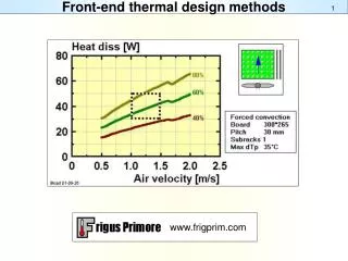
rf properties • Assume pillbox, Cu walls • Q = ~58000 • a=0.574m, L=0.5, f=200MHz • P0 = 1.35 MW • f=200MHz, L=0.5m, E0=10MV/m • U0 = 62J, Tfill = 63.7μs
Buncher rf cavity requirements RF frequency Total voltage cavities Gradient Rf Power 319.63 1.368 1 (0.4m) 4 MV/m 305.56 3.915 2 (0.4m) 5MV/m 293.93 3.336 2 (0.4m) 4.25 MV/m 285.46 4.803 2 (0.45m) 5.5MV/m 278.59 5.724 2 (0.45m) 6.4 MV/m 272.05 6.664 3 (0.45m) 5MV/m 265.80 7.565 3 (0.45m) 5.7MV/m 259.83 8.484 3 (0.45m) 6.5MV/m 254.13 9.405 3 (0.45m) 7MV/m 2.25 248.67 10.326 4 (0.45m) 6MV/m 243.44 11.225 4(0.45m) 6.5MV/m 238.42 12.16 4 (0.45m) 7MV/m 233.61 13.11 4 (0.45m) 7.5MV/m 3.5 98.085 0.2 0.6 0.6 1.0 1.25 1.5 1.5 2 2.25 2.5 3 MW
Rf Rotator/ Cooler requirements • RF Rotator • 56 cavities (15 frequencies) • 12 MV/m, 0.5m • ~2.5MW (peak power) per cavity • Cooling System – 201.25 MHz • 100 0.5m cavities (75m cooler), 15MV/m • ~5MW /cavity
Add Windows effects • ISS had windows … • 200μ Be – 7MV/m cavities • (0.12 MeV energy loss) • 395 μ Be – 10MV/m cavities • (0.24 MeV energy loss) • 750 μ Be – 12.5MV/m cavities (Rotator) • (0.45 MeV energy loss) • MICE rf cavities • 380 μ Be window design • For IDS ?? • Use 200 μ Be for Buncher • Use 400 μ Be for Rotator • Could use Be-grid or “open-cell” ?
Added 0.4mm Be windows in Rotator ~0.24 MeV energy loss/ rf cavity ~13.5MeV total Similar to MICE windows Very small change in “performance” μ/p reduced by 1—2% μ/p ~0.085 Some cooling in rotator εt :: 0.019 0.018 Windows Effects 0.16 All μ εt <0.03 μ 0.08 εt <0.015 0.0
Effect of reduced # of freq in Rotator • First try at reducing number of rf freq. in new RC • Used rf frequency/cavities of the previous table • 400 μ windows in Rotator • Rf phasing set by 233.5 MeV/c particle (?) • Less adapted to actual beam conditions • Somewhat shifted from previous optimization • μ/p reduced from ~0.085 to ~0.081 at z =245m • ~5% worse ?
Variation: lower gradient cooling • Reduce cooling rf to 12 MV/m • From 15 to 16 MV/m • Reduce cooling LiH from 1.1/1.15 cm to 0.8/0.85 • Keep same cooling lattice • Cooling/performance reduced • μ/p at z=245m: 0.0850.070 • εt at z=245m: 0.0710.0845 • At equal cooling ~0.0790.070 • z=220 ~ z= 245m • 65m cooling;90m cooling
Plans etc. • Move toward “realistic” configuration • add Buncher changes • Set up design for cost algorithm • rf cavity design (pillbox, dielectric) • rf power requirements • Magnet design • Continuing front end IDS design study • C. Rogers, G. Prior, D. Neuffer, C. Yoshikawa, K. Yonehara, Y. Alexahin, M. Popovic, Y. Torun, S. Berg, J. Gallardo, D. Stratakis … • ~Biweekly phone Conference • Cost meeting at CERN March • April at Fermilab (IDS meeting) • April 8-10 ??