Download

1 / 24
240 likes | 466 Views
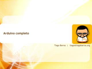
www.arduino.cc. Arduino en DDS. DDS = Direct Digital (frequency) Synthesis. Output = sinusvormig signaal. Maximum frequentie = ½ klokfrequentie. Frequentie bepaald door ‘tuning word’. DDS chips. Grootste fabrikant: Analog Devices (AD9xxx). Voorbeeld: AD9850 (Analog Devices).

E N D
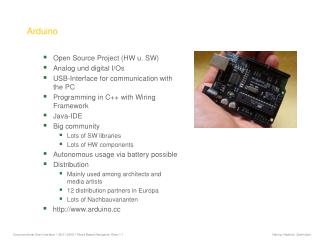
DDS = Direct Digital (frequency) Synthesis • Output = sinusvormig signaal • Maximum frequentie = ½ klokfrequentie • Frequentie bepaald door ‘tuning word’ DDS chips • Grootste fabrikant: Analog Devices (AD9xxx)
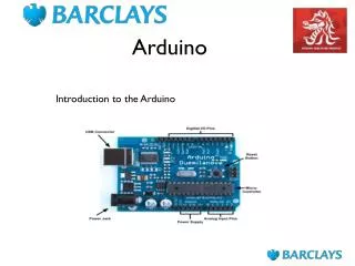
Voorbeeld: AD9850 (Analog Devices) CLKIN = systeemklok, max. 125 MHz DGND, DVDD: voeding digitaal AGND, AVDD: voeding analoog D7, W_CLK, FQ_UD tuning word upload (32 bits) IOUT = analoge signaaluitgang Max. frequentie: 125/2 = 62,5 MHz DDS chips Frequentiestap: tot 0,0291 Hz Frequentievariatie: tot 23 M per seconde 28-SSOP (Shrink Small Outline Package)
Voorbeeld DDS-board DDS chip AD9850
Het ‘tuning word’ Δ Phase bepaalt de uitgangsfrequentie: fOUT = (Δ Phase x CLKIN) / 232 Of: Δ Phase = (fOUT x 232) / CLKIN Δ Phase = waarde van het tuning word DDS chip AD9850 CLKIN = frequentie van de systeemklok (bv. 120 MHz) fOUT = uitgangsfrequentie Voorbeeld voor 3,6 MHz: Δ Phase = (3,6 x 232) / 120 Δ Phase = 128849018,88 ~ 128849019 fOUT = (128849019 x 120) / 232 = 3,600000003 Tuning woord binair: 111101011100001010001111011
Hoe wordt het ‘tuning word’ geladen? 2 mogelijke manieren • Parallel: 5 x 8 bits via D0-D7 pennen. Wordt hier niet verder beschouwd. • Serieel: 40 bits, bit per bit via D7, in de juiste volgorde en met de juiste timing. DDS chip AD9850
Serieel laden van het tuning woord: volgorde en timing 40-bit data bit per bit laden via pen 25 D7 Volgorde LSB (least significant bit) first: laagstbeduidende bit eerst Timing: 1 bit per W_CLK puls, na 40 bits FQ_UD puls DDS chip AD9850
Serieel laden van het tuning woord: 40-bit? DDS chip AD9850 Bits 0-31 = tuning word (frequentie) Bits 32-39 zijn controlebits: op 0 plaatsen (voor AD9850)
Opdracht: Genereer frequenties tussen 1 en 10 kHz Hardware setup Verbind FQ_UD (pen 8) van de AD9850 met I/O 8 van de Arduino Verbind W_CLK (pen 7) van de AD9850 met I/O 9 van de Arduino Verbind D7 (pen 25) van de AD9850 met I/O 10 van de Arduino Sluit een scoop aan op Iout (pen 21) van de AD9850 Verbind de Arduino met de USB-poort van de PC SWEEP9850
Genereer frequenties tussen 1 en 10 kHz • Start de Arduino IDE • Check Tools/Board en Tools/Serial • Voer de volgende lijnen in: • // Frequentiesturing van een AD9850 DDS door het berekenen en serieel laden van een 40-bit datawoord • #define DDS_CLOCK 120000000 // frequentie van de DDS-klok (in Hz) • byte LOAD = 8; // I/O 8 is verbonden met FQ_UD van de DDS • byte CLOCK = 9; // I/O 9 is verbonden met W_CLK van de DDS • byte DATA = 10; // I/O 10 is verbonden met D7 van de DDS SWEEP9850 • Alles na // is commentaar (veelvuldig gebruiken!) • #define DDS_CLOCK 120000000: tijdens de compilatieslag zal DDS_CLOCK in de broncode vervangen worden door 120000000, de frequentie van de systeemklok. • Byte LOAD = 8 LOAD is de naam voor de bytewaarde 8
Voeg de volgende regels toe: void setup() // deze instructies worden eenmaal uitgevoerd { // Plaats alle I/O pennen in OUTPUT mode pinMode (DATA, OUTPUT); pinMode (CLOCK, OUTPUT); pinMode (LOAD, OUTPUT); } • pinMode() bepaalt of de Arduino I/O-poort in kwestie zich moet gedragen als input- of outputpoort. In dit geval sturen al deze poorten data naar de AD9850, dus OUTPUT. • Deze instructies worden eenmaal uitgevoerd SWEEP9850
Voeg de volgende regels toe: void loop() // deze instructies worden doorlopend uitgevoerd { // Doe een frequentiezwaai tussen 1 en 10 kHz in stappen van 1 Hz for(unsigned long freq = 1000; freq < 10000; freq++) { sendFrequency(freq); delay(2); } } • void loop() : deze instructies worden continu uitgevoerd • for-loop: • for (vanaf; test; stap) • { instructies} • Voer de instructies uit vanaf freq = 1000 zolang freq < 10000 • Verhoog freq met 1 na elke lusdoorloop SWEEP9850
Voeg de volgende regels toe: void sendFrequency(unsigned long frequency) { // Bereken het datawoord unsigned long tuning_word = (frequency * pow(2, 32)) / DDS_CLOCK; // Zet W_CLK laag digitalWrite(CLOCK, LOW); // Zet FQ_UD laag digitalWrite(LOAD, LOW); // Klok de eerste 8 bits in het register van de DDS (W0-W7) shiftOut(DATA, CLOCK, LSBFIRST, tuning_word); // Klok de volgende 8 bits (W8-W15) shiftOut(DATA, CLOCK, LSBFIRST, tuning_word >> 8); // Klok de volgende 8 bits (W16-W23) shiftOut(DATA, CLOCK, LSBFIRST, tuning_word >> 16); // Klok de volgende 8 bits (W24-W31) shiftOut(DATA, CLOCK, LSBFIRST, tuning_word >> 24); // Klok de volgende 8 bits = 0 (W32-W39) shiftOut(DATA, CLOCK, LSBFIRST, 0x0); // Zet FQ_UD hoog om het datawoord door te schuiven in de DDS (= nieuwe frequentie) digitalWrite(LOAD, HIGH); // Take load pin high again } SWEEP9850
unsigned long tuning_word = (frequency * pow(2, 32)) / DDS_CLOCK Bereken het ‘tuning word’: Δ Phase = (fOUT x 232) / CLKIN digitalWrite(CLOCK, LOW) digitalWrite(LOAD, LOW) Plaats de poorten CLOCK en LOAD op LOW shiftOut(DATA, CLOCK, LSBFIRST, tuning_word) shiftOut: shifts out a byte of data one bit at a time. Starts from either the most (i.e. the leftmost) or least (rightmost) significant bit. Each bit is written in turn to a data pin, after which a clock pin is pulsed (taken high, then low) to indicate that the bit is available. shiftOut(DATA, CLOCK, LSBFIRST, tuning_word >> n) >> n: schuift het datawoord n bits naar rechts shiftOut(DATA, CLOCK, LSBFIRST, 0x0) Niet vergeten om de controlebits 32-39 (waarde 0) te laden digitalWrite(LOAD, HIGH) Ten slotte: FQ_UD hoog plaatsen om het datawoord door te schuiven SWEEP9850
Datatypes unsigned long ? byte ? Andere datatypes: zie reference manual (selecteer Help /Reference in IDE)
HOP9850 Opdracht: Frequenties instellen met een schakelaar Schakelstand A1 = 50,040 MHz A2 = 50,041 MHz A3 = 50,042 MHz
HOP9850 byte switchA1 = 11; // I/O 11 is verbonden met schakelaar A, pen 1 byte switchA2 = 12; // I/O 12 is verbonden met schakelaar A, pen 2 byte switchA3 = 13; // I/O 13 is verbonden met schakelaar A, pen 3 unsigned long freq1 = 50050000; unsigned long freq2 = 50051000; unsigned long freq3 = 50052000; int switchNu = 1; int switchVorig = 0;
HOP9850 pinMode (switchA1, INPUT); // via I/O 11 wordt de status van de schakelaar pen 1 gelezen pinMode (switchA2, INPUT); // via I/O 12 wordt de status van de schakelaar pen 2 gelezen pinMode (switchA3, INPUT); // via I/O 13 wordt de status van de schakelaar pen 3 gelezen
HOP9850 void loop() { if (digitalRead(switchA1) != 0) // schakelaar A1 hoog? switchNu = 1; if (digitalRead(switchA2) != 0) // schakelaar A2 hoog? switchNu = 2; if (digitalRead(switchA3) != 0) // schakelaar A3 hoog? switchNu = 3; if (switchNu != switchVorig) // als de schakelstand gelijk is: niets uitvoeren { switch (switchNu) { case 1: // A1 is gesloten sendFrequency(freq1); break; case 2: // A2 is gesloten sendFrequency(freq2); break; case 3: // A3 is gesloten sendFrequency(freq3); break; } switchVorig = switchNu; delay (1000); } }
FSKCW9850 Vakantietaak Genereer “ON6MS JO10UX” in morse op 28,350 MHz, FSKCW shift 170 Hz, 8 wpm • Hardware setup: zoals bij Sweep9850 (3 lijnen) • Software: zie infoblad • Maak een analyse van het programma