Download
1 / 54
700 likes | 1.16k Views
Actuators for Robots. Actuators are used in order to produce mechanical movement in robots. Actuators. In this lecture we will present: Motor and Encoder H-Bridge Pulse-Width-Modulation (PWM) Servos Other robotic actuators. Actuator Types. Electrical Hydraulic Pneumatic Others.

E N D
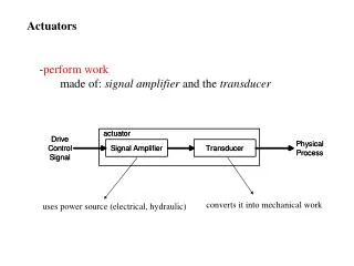
Actuators for Robots Actuators are used in order to produce mechanical movement in robots.
Actuators In this lecture we will present: Motor and Encoder H-Bridge Pulse-Width-Modulation (PWM) Servos Other robotic actuators
Actuator Types Electrical Hydraulic Pneumatic Others
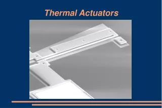
Actuators • Actuators can be built in may different ways, most prominently: • electrical motors • pneumatics and valves. • In this course we will only deal with electrical motors • In past we built pneumatic robots which you can still find in the lab. • We will build them again after purchasing air compressor • My first robot was very strong and it was hydraulic. It pissed hot oil at students in Warsaw.
Servo System Servo is mechanism based on feedback control. The controlled quantity is mechanical.
Properties of Servo high maximum torque/force allows high (de)acceleration high zerospeed torque/force high bandwidthprovides accurate and fast control works in all four quadrants robustness
Electrical Actuators easy to control from mW to MW normally high velocities 1000 -10000 rpm several types accurate servo control ideal torque for driving excellent efficiency autonomous power system difficult
Electric actuators • Mainly rotating but also linear ones are available • linear movement with gear or with real linear motor
DC-motors brushless DC-motors asynchronous motors synchronous motors reluctance motors (stepper motors)
DC-Motors simple, cheap easy to control 1W - 1kW can be overloaded brushes wear limited overloadingon high speeds
DC-motor control Controller + H-bridge PWM-control Speed control by controlling motor current=torque Efficient small components PID control
H-Bridge Hardware Implementation with Microcontroller: 2 Digital output pins from microcontroller, [one at Gnd, one at Vcc] feed into a power amplifier Alternative: use only 1 digital output pin plus one inverter, then feed into a power amplifier
Brushless DC-Motors (pm synchronous motor) no brushes no wearing parts high speeds coils on cover => better cooling excellent power/weight ratio simple needs both speed and angle feedback more complicated controller From small to medium power (10W – 50kW)
Asynchronous Motors very simple, very popular in industry 0,5kW - 500kW More difficult to control (frequency) nowadays as accurate control as DC-motors In mobile machines also (5kW )
Synchronous Motors usually big 100 kW - XXMW also small ones ~ brushless DC-motors from 50W to 100 kW controlled like as-motors (frequency) ships industry Mobile machines
Reluctance (Stepper) Motors angle control slow usually no feedback used accurate positioning with out feedback not servos easy to control
Stepper Motors • Stepper motors are another kind of motors that do not require feedback • A stepper motor can be incrementally driven, one step at a time, forward or backward • Stepper motor characteristics are: • Number of steps per revolution (e.g. 200 steps per revolution = 1.8° per step) • Max. number of steps per second (“stepping rate” = max speed) • Driving a stepper motor requires a 4 step switching sequence for full-step mode • Stepper motors can also be driven in 8 step switching sequence for half-step mode (higher resolution) • Step sequence can be very fast, the the resulting motion appears to be very smooth
Stepper Motors • Advantages • No feedback hardware required • Disadvantages • No feedback (!) Often feedback is still required, e.g. for precision reasons, since a stepper motor can “lose” a step signal. • Requires 2 H-Bridges plus amplifiers instead of 1 • Other • Driving software is different but not much more complicated • Some controllers (e.g. M68332) support stepper motors in firmware (TPU)
Motor and Encoder Motor speed determined by: supplied voltage Motor direction determined by: polarity of supplied voltage Difficult to generate analog power signal (1A ..10A) directly from microcontroller → external amplifier (pulse-width modulation)
Motor and Encoder Encoder disk is turned once for each rotor revolution Encoder disk can be optical or magnetic Single detector can determine speed Dual detector can determine speed and direction Using gears on motor shaft increases encoder accuracy
Pulse-Width Modulation • A/D converters are used for reading analog sensor signals • Why not use D/A converter for motor control? • Too expensive (needs power circuitry) • Better do it by software, switching power on/off in intervals • This is called “Pulse-Width Modulation” or PWM
Pulse-Width Modulation • How does this work? • We do not change the supplied voltage • Power is switched on/off at a certain pulse ratio matching the desired output power • Signal has very high frequency (e.g. 20kHz) • Motors are relatively slow to respond • The only thing that counts is the supplied power • ⇒ Integral (Summation) • Pulse-Width Ratio = ton / tperiod
Servos Terminology: Do not confuse “servos” with “servo motors” DC motors (brushed or brushless) are also sometimes also referred to as “servo motors” See: http://www.theproductfinder.com/motors/bruser.htm “So when does a motor become a servo motor? There are certain design criteria that are desired when building a servo motor, which enable the motor to more adequately handle the demands placed on a closed loop system. First of all, servo systems need to rapidly respond to changes in speed and position, which require high acceleration and deceleration rates. This calls for extremely high intermittent torque.
Servos • As you may know, torque is related to current in the brushed servo motor. • So the designers need to keep in mind the ability of the motor to handle short bursts of very high current, which can be many times greater than the continuous current requirements. • Another key characteristic of the brushed servo motor is a high torque to inertia ratio. • This ratio is an important factor in determining motor responsiveness. • Further, servo motors need to respond to small changes in the control signal. • So the design requires reaction to small voltage variations.”
Hydraulic Actuators HUT/Automation linear movement big forces without gears actuators are simple in mobile machines Bad efficiency motor, pump, actuator combination is lighter than motor, generator, battery, motor & gear combination
Hydraulic Valves • servo valves • complicated structure, expensive • good control • proportional valves • simple, cheap • robust • more difficult to control • Digital hydraulics, new! • several fast on/off valves (2n) • digital control of the flow
Pneumatic Actuators • like hydraulic except power from compressed air • fast on/off type tasks • big forces with elasticity • no leak problems
Other Actuators piezoelectric magnetic ultra sound SMA inertial