Download
1 / 23
330 likes | 791 Views
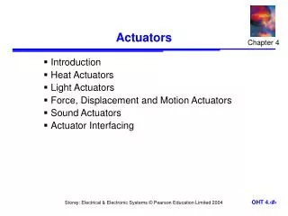
Actuators. Actuators. Hardware devices that convert a controller command signal into a change in a physical parameter The change is usually mechanical (e.g., position or velocity) An actuator is also a transducer because it changes one type of physical quantity into some alternative form

E N D
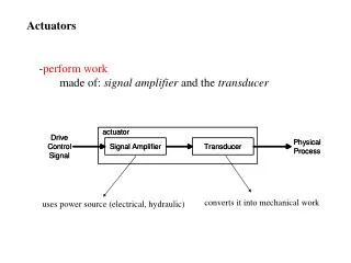
Actuators Hardware devices that convert a controller command signal into a change in a physical parameter • The change is usually mechanical (e.g., position or velocity) • An actuator is also a transducer because it changes one type of physical quantity into some alternative form • An actuator is usually activated by a low-level command signal, so an amplifier may be required to provide sufficient power to drive the actuator
Actuators Mechanism Signal Processing & Amplification Hydraulic Pneumatic Electric Final Actuation Element Logical Signal Actuator Sensor
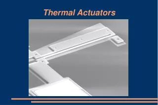
Types of Actuators • Electrical actuators • Electric motors • DC servomotors • AC motors • Stepper motors • Solenoids • Hydraulic actuators • Use hydraulic fluid to amplify the controller command signal • Pneumatic actuators • Use compressed air as the driving force
Principles • Current passing through a helical coil winding of closely spaced turns of copper magnet wire produces a magnetic field which surrounds the coil. • If an iron structure is assembled around the winding, the magnetic force is channeled through the metal and is considerably increased because of the magnetic permeability of the iron. • All solenoids develop magnetizing force, which has a relationship to the current and number of turns in the coil.
Applications • Automotive • Linear Movement • Small Valve Mechanisms • Flow Control • Non-Stick Latches • Anywhere where fast linear movement is required
How it works (continued) Example 1 –Valve A spring maintains the valve in its closed or open position. When a current is passed through the coils around the core, it will produce a magnetic force, that pushes the valve to the Open or closed position. When the current is stopped The force is removed and The valve moves to its original Position.
Major Specifications – Selection Factors • Voltage • Duty cycle- Specifies the length of time the solenoid coil is to be electrically energized and de-energized. • Current and Power • Temperature • Stroke – Distance the plunger must travel • Force – Push or pull energy the actuator must exert • Mounting and Environment – Coil heat is bad for the Solenoid
Limitations • Temperature of device may increase very fast • Limited to current input possible • Limited to force of actuator • Large force = Lots of money • Must be mounted very firm • Must control with PWM or AC
Advantages • Very strong • Very fast • Very customizable to specifications • Several Manufacturers • Great for high power short bursts
Types of Solenoids • Linear • Rotary • Long Stroke • Micro Machine • High Power
The Principle Behind Electromechanical Relays A relay is similar to a switch, it is either open or closed. When the switch is open no current passes through the relay, the circuit is open, and the load that is connected to the relay receives no power. When a relay is closed, the circuit is completed and current passes through the relay and delivers power to the load. To open and close a relay an electromagnet is used. When the coil controlling the electromagnet is given a voltage, the electromagnet causes the contacts in the relay to connect and transfer current through the relay.
Electromechanical Relays: What’s Inside This diagram shows the basic parts of an electromechanical relay: a spring, moveable armature, electromagnet, moveable contact, and stationary contact. The spring keeps the two contacts separated until the electromagnet is energized, pulling the two contacts together. Moveable Contact Moveable Armature Stationary Contact Spring Electromagnet
Wiring Up an Electromechanical Relay This diagram shows how to wire an electromechanical relay. When the control circuit turns the electromagnet on, the moveable armature is drawn towards the electromagnet and connects the moveable contact and the stationary contact. This completes the circuit and delivers power to the load. Power Supply Load Moveable Contact Moveable Armature Stationary Contact Spring Electromagnet To Control Circuit
Typical Sample Application Suppose, there is a need to control a solenoid valve for a water drain application. Control is to be accomplished with a microcontroller. The solenoid valve requires 120 VAC to open. Assuming that a 120 VAC power supply is available, how can control of the solenoid valve be accomplished using a microcontroller that can only supply 5 VDC? This problem is easily solved using a relay. There are many relays that are turned on and off with a 5 VDC coil. The relay provides the interface between the microcontroller and the 120 VAC power supply that is needed to open and close the valve.
Typical Sample Application Ground To Microcontroller Coil Relay 120 VAC Solenoid Valve Circuit for Control of a 120 VAC Solenoid Valve
Electromechanical Relay Advantages • Contacts can switch AC or DC • Low initial cost • Very low contact voltage drop, thus no heat sink is required
Electromechanical Relay Limitations • The contacts wear and thus have limited life depending on loads • Short contact life when used for rapid switching applications or high loads • Poor performance when switching high inrush currents • Package Size
Important Specifications of Electromechanical Relays • Coil Voltage – Voltage required for switching • Contact Rating – How much current the relay can handle • Normally Open (NO) or Normally Closed (NC)